This thread has been locked.

If you have a related question, please click the "Ask a related question" button in the top right corner. The newly created question will be automatically linked to this question.

LMH6552: dc-coupled ADC driver

Part Number: LMH6552
Other Parts Discussed in Thread: THS4509, , OPA695, LMH6702, ADS5553, OPA659, THS4541, TINA-TI

Hello

I want to use LMH6552 or THS4509 as an ADC driver in dc-coupled and single ended topology.

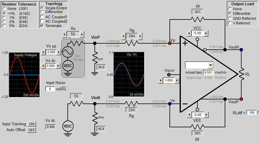
the gain is 0.5V/V and the source is 2Vpp and 50 Ohm.  (Rf=301 Rg=294 Rt=56.9)

but the source has a little output offset. (some mV maximum)

I've studied in some application notes and datasheets that I should apply some equal DC voltage at the inputs of the FDA.

I can not measure the output offset very accurate.

how should I provide this voltage and apply it at the second input of the FDA?!!!


Best Regards

  • Hello xyz xyz,

    Both of those amplifiers are suitable for a DC coupled ADC driver.  Can you specify the ADC you are using?  What do you mean by single ended?  Is the ADC input single ended? 

    What is the common mode of the input signal?  What is the common mode of the ADC?

    Typically we advise to set the amplifier with the power supplies symmetrical around the ADC common mode, and set the common mode input to this voltage.

     The input voltage is then offset from the output voltage.  This offset is divided across the Rg and Rf resistors.

    It may be worth looking at single ended operational amplifiers like the LMH6702 or the OPA695 for this application.  You can still  manage a DC shift with your termination resistor. 

    Both the LMH6552 and THS4509 have schematics in the datasheets that show how to drive the second FDA input. 

    I can give more advice once I know for sure what kind of circuit you will be using.

    Regards,

    Loren

  • Dear

    Single ended topology is:

    http://www.ti.com/download/kbase/adc/DifGain.htm

    (or you can use DiffAmp Calc v3.1.1 by Analog Devices)

    ADS5553

    FDA spec: Vocm=1.65V Vcc=+5 and Vee=0

    the source is 2Vpp and 50 ohm

    in DC coupled topology I should apply some dc level to the second input of FDA.

    but my problem is:

    DC offset of the first input is some mV.

    for example I have a 50 Ohm cable driver with OPA659. but the DC level at the output of OPA659 is some mV. I want to connect this coax cable to the FDA in dc-coupled topology .

    for some mV is it necessary to provide this DC level at the second input of the FDA?

    Regards

  • don't you have any suggestion?

    Thanks
  • Hello xyz xyz,

    Is it possible to use a negative power supply, like -2.5V?  This will give you much more flexibility.  Having 0.851V on the amplifier input pins is close to the negative supply voltage and will increase the distortion.   It will also be the same with the output voltage of 1.65V even though the swing is only 0.5Vpp.  

    In your example, you have a Vs DC of 0V on both amplifier inputs that is good in that both inputs have the same voltage, but it is pretty low given the 0V and 5V power supply.  

    One of the best ways to evaluate our amplifiers is to use the TINA-TI simulation program and do a transient simulation.  I made a test circuit of your proposed circuit and it shows that the amplifier needs a negative power supply to operate with the 1.65V common mode.  We do have amplifiers like the THS4541 which are designed to operate in a circuit similar to yours, but it is not as fast as the LMH6552.  

    LMH6552_ADC_Driver.TSC

    Regards,

    Loren

  • I really appreciate you for your attention and recommendation.
    actually I can put a 1uF capacitor at the input of FDA (I mean ac-coupled) but when I check the frequency response there is a peaking at the inputs of the FDA! but it's disappeared at the output of the FDA :) but you can still see the peaking at the noise analysis :)

    the peaking is near to the cut-off frequency of the input of the FDA.

    Thanks