This thread has been locked.
If you have a related question, please click the "Ask a related question" button in the top right corner. The newly created question will be automatically linked to this question.
Hi,
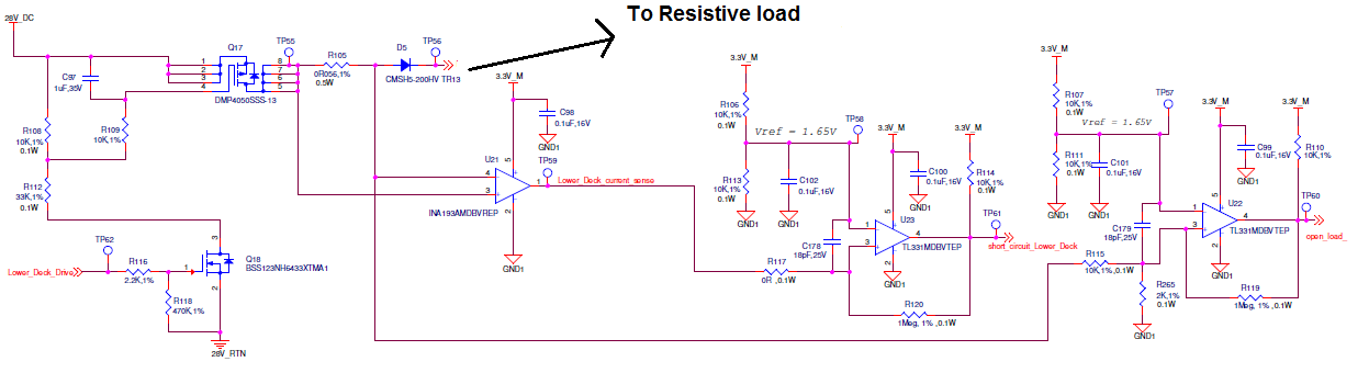
I am using INA193 for load current sensing on high side Mosfet drive. and as per my requirement we are using it to sense short circuit current.
As per my application the load current requirement is 1Amp. and i have set the short circuit limit to 1.5Amp.The load is driven at 28V from a high side P-channel mosfet.
when we performed short circuit test we found that few of the INA193 gone bad.
What could be the reason for failure of the INA193.
Thanks
Rahul Wagh
Hi Rahul,
We would have to analyse the waveforms with an oscilloscope to know exactly what is happening.
In regards to the part being damaged, would you be able to clarify your observations, in particular:
Did the part failed completely or does it still operate, albeit erroneously?
If the latter can you describe what was the expected and observed behaviour?
Did replacing with a new part fixed the issue or did the new part also failed after a period of operation? If the latter, has it failed in a similar way to the part before?
What are the values of your circuit components (RS, supply peak current, any electrolytic caps, etc)?
Under a short circuit, there is the possibility that the whole supply voltage can become present across Rs, which could potentially exceed the maximum rating of the INA193. Differentially, that is +/-18V. Its also note considering any parasitic inductance on the circuit that can cause a voltage overshoot when the mosfet opens the circuit.
The INA180 datasheet specs some guidelines you might find useful when designing some protection circuit.
Hi Carlos,
Thanks for the reply.
Please find below my observation on the part failure
We have observed failure in 4nos. of INA193 out of 10nos. used in the product.
During initial testing when the part failure observed below is our observation.
Now I have tested the board with supplying only 3.3V to it even I have not supplied 28V DC to the board and I have captured the waveforms and observed the same that the output voltage is reaching to 2V after power onand it starts decaying to 0V in around 140sec.
After replacing with new part has resolved the issue and we have not perfomed much operation after replacement.
I doubt that the we have exceeded the +/-18V input voltage limit as we did not do the short fully as only increased the current to 1.5Amp by reducing the load resitor to <33ohm.
I am attaching the circuit of our application, as per our requirment we are supplying 28V DC to the external load which is currenly a resitive load of 33ohm@28V(having 1uf cap. In parallel to it), and in actual field it will be indutive load.
I am attaching the four waveform of the 4 parts failure which we observed, out of that one waveform has increase in the voltage rather than decrease in voltage.
Thanks
Rahul Wagh
Hi Rahul,
Thank you for bearing with me while I checked this issue.
First I would like to fully understand the circuit operation.
Hi Carlos,
Your understanding is correct on the circuit.
U23 is comparing the voltage received from INA193 and reference voltage Vref=1.65V, the output of the U23 is sensed by the intellegent deivce which turns off the Q18 and Q17. With U22 we are just sensing the load voltage and comparing it.
Both the ground are shorted with ferrite bead, so for DC both ground GND1 and 28V_RTN are shorted in our circuit.
As you have asked i have tested the by removing R117 and Q27 and with a load current of 0.6A Amp. flowing through R105, and even then i have observed the same waveform as the output voltage of INA193 is decaying from 2V to 0V in 100sec.
Thanks & Regards
Rahul Wagh
Thank you for providing more details on this issue. I will follow up shortly, Rahul.
This seems like a task very well suited for the INA302 or INA303. I suggest you have a look at these devices