This thread has been locked.

If you have a related question, please click the "Ask a related question" button in the top right corner. The newly created question will be automatically linked to this question.

INA168-Q1: Minimum Vsense voltage of INA168-Q1

Part Number: INA168-Q1

Hi team,

What's the Vsense input minimum voltage of INA168-Q1 with 100mohm Rs?   

Because when my customer set load Is=10mA, means Vsense=Rs*Is=1mV only. In that case, the output voltage is not s expected.  Can our device work properly under Vsense<1mV ?

  • Hi Lilian,

    The part offset voltage is given in the datasheet as up to +/- 1mV therefore we cannot guarantee correct operation under Vsense = 1mV.

    Under the product page, for the INA 168 there is an error calculator. In fact even at 50mA with Rsense = 100mR the output error is still 25%.

    I might be able to better suggest a more suitable part. What are the operating conditions of your application and the required gain?
  • Hi Carlos,

    Thanks for your reply.
    If my customer still want to use this part, can they increase Rsense value(e.g. 1ohms), so that the minimum Vsense will be more than 1mV?
  • Hi Carlos,

    I just confirmed with my customer, Rsense has to be 0.1ohm because they must ensure maximum output voltage <3V. ( Maximum current through Rs is 2A, and RL=75K).  Let's forget the proposal of increasing the Rsense...

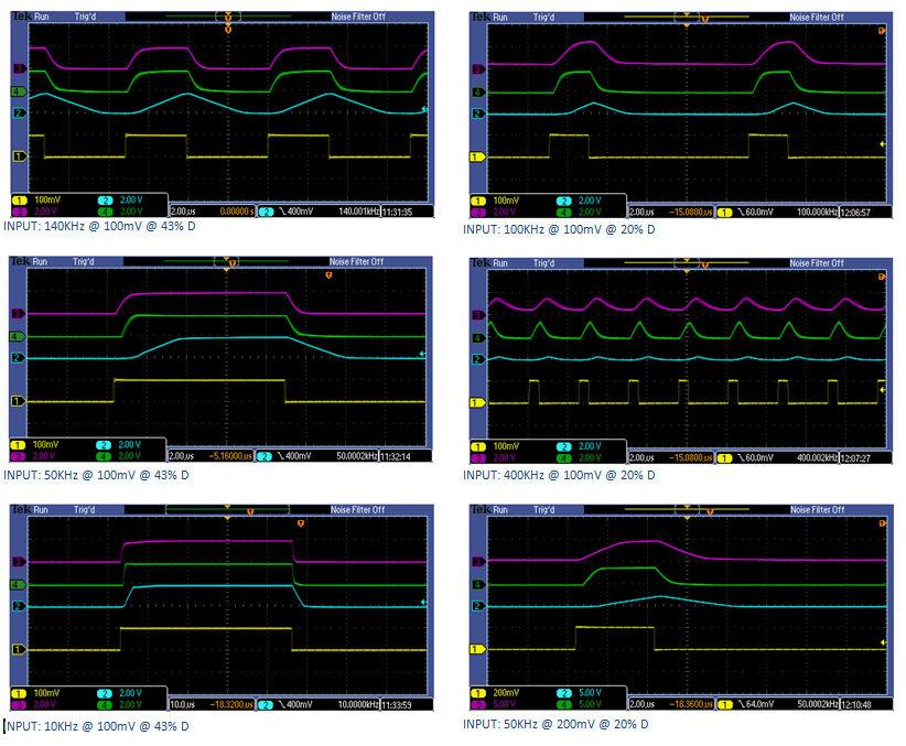
    Another question is what's the GAIN in the datasheet stand for? Means gm?  Because, we found that if the INA168-Q1 work under 2mA current with 100K~1M ripple freq. then the output voltage is not correct.  Could it because of the freq response with different gain?     

  • Hi Lilian,

    Gain changes with frequency due to the output slew rate limitation, as with any opamp. This is a compromise. Too much slew rate may lead to unwanted high frequency oscillations, too little acts as a filter to the output signal. I might be able to best sugest if you describe your application requirements.

    For reference here are a few plots of different outputs for current sense amplifiers with different slew rates and how these affect output (and gain) at various frequencies or duty cycles. The Yellow plot is the input waveform.