This thread has been locked.
If you have a related question, please click the "Ask a related question" button in the top right corner. The newly created question will be automatically linked to this question.
Hello everyone,
now i want to generate the 1MHz Triangular waveforms and i have seen an idee in the paper as follows. It consists of a comparator (A) and an integrator (B) as shown.
Because the frequency of my generated triangular waveform is 1MHz. I have seen the datasheet of LM741. But i also don't konw, whether i can use LM741 as coparator and integrator to generate this triangular waveform. If not, can you recommand me a useful IC or amplifier for my use?
Thank you so much for your help!
Best regards
Hi Ronald,
thank you for your reply.
I have seen the datasheet of LM741 and i can also supply 15V voltage or 5V. The desired amplitude is 0.5*LSB or LSB, namely 3e-6 V or 6e-4 V. But the most important is, the frequency of triangular waveform with 1MHz.
Best wishes,
Jackie
Part Number: LM741
Hello everyone,
now i want to generate the 1MHz Triangular waveforms and i have seen an idee in the paper as follows. It consists of a comparator (A) and an integrator (B) as shown.
Because the frequency of my generated triangular waveform is 1MHz. I have seen the datasheet of LM741. But i also don't konw, whether i can use LM741 as coparator and integrator to generate this triangular waveform. If not, can you recommand me a useful IC or amplifier for my use?
Thank you so much for your help!
Best regards
Jackie
Jackie,
Here is the TI-Tina circuit that is close to 1 MHz.
It could use some tweaking to get different frequencies and amplitudes.
Hi Ronald,
thank you so much for your so patient help!
You mean that i can't use LM741 to generate the triangular waveform with 1MHz, because LM741 with 1.5MHz bandwidth is only enough for the ideal case.
But i still don't know if my schematic as below valid is or not for my purpose? And as you suggested, A(comparator) is TLV3201 and B(integrator) is TLV3541.
I am looking forward to your kindly reply.
Thanks again!
Jackie
Hi Ronald,
i have just seen your useful file "triangle.TSC". Thank you so much for your help!
But i don't know why you use middle voltage rather than direct ground for the comparator and integrator? And i don't know how to calculate the amplitude and frequency in your circuit.
In my circuit i know the theory for the amplitude and frequency as below:
But if i use the same formula as in this paper. I can't get the amplitude 3e-4 V or 6e-4 V and the frequency 1MHz.
So can you tell me how to calculate the amplitude and frequency in your circuit? Or if my circuit is also valid, is it simpler to achieve my purpose?
Thanks a lot!
Jackie
Hi Ronald,
thank you for your circuit. I have tried it and the frequency is now close to 1MHz. But now i have problem about the amplitude.
I want to generate the amplitude of the triangular wave close to +-0.3 mV. But if i use your circuit, then i can't generate negative voltage. So i change the circuit as my theory in the paper as below.
And then i can get positive and negative amplitude. But no matter how i change the resistor and the capacitor, the minimal amplitude is +-2.7 mV as below.
So i can't generate +-0.3 mV amplitude. Do you have any suggestion? Maybe we should try other amplifier as comparator and integrator?
My file is attached.
I am looking forward to your reply. Thank you so much for your help!
Jackie
Hi Ronald,
now i have a more important question. Do you know which single chip or single IC to generate directly the triangular waveform with 2MHz? Because it's simpler in this way.
I have known one such as MAX038. Do you know other good ICs in Texas Instrument for my purpose?
Thanks a lot!
Jackie
Jackie,
It is better to have a larger triangle wave and AC couple and attenuate to get +/-0.3mV
Hi Ronald,
thank you so much for your help.
As your suggestion i want to use TLV3201 and TLV3541 to generate triangular waveform with 2MHz and +-0.6mV.
But i have forgotten to tell you my goal. In our university we want to use the ICs to generate triangular waveform as Dithering signal. And this Dithering signal can help to make the performance of ADC better. This is our goal. In this way, is it also good to use TLV3201 and TLV3541? Or you have any other better suggestion?
I have found two files as attached in your company. Is it also helpful for my purpose?
I am looking forward to your reply and thanks so much for your help in advance!
Best regards,
Jackie
Hi Ronald,
i have tried both of the solutions, it works but maybe not so optimal. Maybe the value of the capacitor is not so optimal. My file have been attached, can you help me to see it one more time?
Thanks a lot!!
Jackie
i Ronald,
thank you very much for your help.
Now i think the triangular generator works also well without the additional capacitor.
But now i want to use this triangular waveform added to a voltage signal and i need a amplifier as adder.
I have seen two methods in TI website, namely inverting adder and non-inverting adder as below.
But there are so many amplifier in TI and i have tried some but failed. So i want to ask for your help to select a suitable amplifier as adder.
I think direct adder is better, because if we use inverting adder, after that maybe we need one more amplifier as inverter.
Thanks for everything and looking forward to your reply.
Noninverting Adder and Dither.TSC
Best regards,
Jackie
Hi Ronald,
i think i have found the suitable amplifier as summing amplifier, namely OPA684.
But i don't know why the sum result is not correct yet. Both non-inverting and inverting adder work not well.
I need your help. Really appreciate for it!
6471.Noninverting Adder and Dither.TSC
Inverting Adder and Dither.TSC
Best regards,
Jackie
Hi Ronald,
thank you for your advice and sorry to bother you so much.
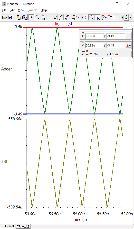
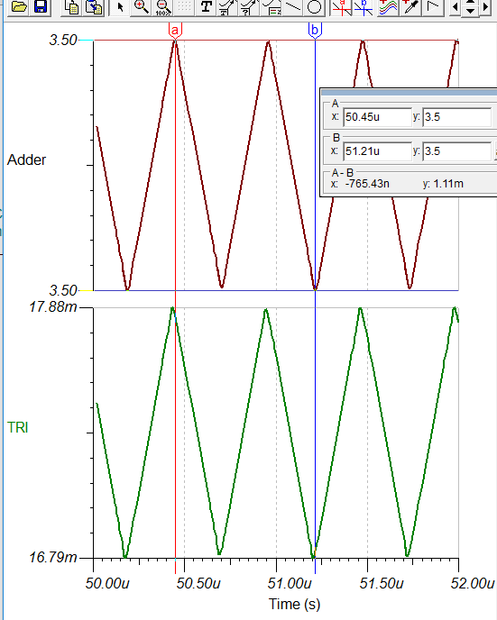
I have tried many times and finally i added a -5V as source for OPA684 and left 8th pin of OPA684 open. I think it works now but not so well as follows. The two inputs are 5mV and triangular wave with +-0.6mV, the Adder stands for the sum of these two inputs.
But if i connected the 8th Pin of OPA684 to VCC 5V, then the waveform of the Adder is better but not correct sum of the two inputs as below. So i don't know how to make the waveform better and at the same time get a right sum of the inputs. Do you have any solution?
Thanks a lot!!
Jackie
Hi Ronald,
"Let's see if I understand correctly. You want to make a summer where the output is the sum of both inputs with a gain of 1 (0db) for each input." Your Understanding is correct.
Yes, because the TRI signal is one half of period is positive, the other half is negative. The amplitude is +-0.6mV, frequency is 2MHz. So i don't care the final output is IN+TRI or IN-TRI.
And the IN signal is normal voltage signal, variable between -5V and +5V.
If the output is IN+TRI, then i can directly use the output.
If the output is -(IN-TRI), then i will make an inverse of it. So in this case my goal is IN-TRI.
So i hope the sum is more correct! Either IN+TRI or IN-TRI. Now my result file is not so accurate as below.
2577.Inverting Adder OPA684_2.TSC
Thanks a lot!
Jackie
Hi Ronald,
Thanks! It's really a good news.
I have tried your circuit and it's perfect!
There is only one more little problem: the amplitude of my triangular wave is changed. If i add a capacitor with 1nF between the “TRI” output and the adder circuit, then the amplitude of my triangular wave is correct, namely 0.6mV. But in this way the output of "Adder" is not correct any more. So i don't how to solve it.
Thank you for everything!
Best regards,
Jackie
Jackie,
R1 sets frequency and R7 sets amplitude.
Using new standard value for R7, amplitude is now +/-0.59mV (1.18mVpp)
I added VM1 meter to make "adder" output amplitude easier to see.
'Adder' output DC voltage is 3.4995V higher than VM1 reading .
Hi Ronald,
thank you so much for your help!! You are the best expert!
I have seen the result of the circuit and it's perfect.
But i have one more question. Why the output of TRI is not +-0.6mV, but the output of Adder is the sum of input and +-0.6mV?
And why you select OPA350 instead of OPA684 and why you choose noninverting summing circuit, not the inverting summing circuit. Is there a reason? Because i have heard that inverting summing circuit performs better than noninverting summing circuit. Is it true?
Thanks and best wishes,
Jackie
Hi Ronald,
i have just found one problem.
My most important purpose is to make the average of positive and negative amplitude of triangular wave equal zero. But maybe this average of positive and negative amplitude of triangular wave in your non-inverting summing circuit is not zero and variable. I know it's hard to make the average null in practical case. But if it's a constant error, then i can solve it in FPGA. But it's a variable error, then it's a big trouble.
In your non-inverting circuit the amplitude of triangular waveform varies with the input? Perhaps because this is no capacitor between them.
I think in this way maybe the old inverting summing circuit performs better?
1222.Inverting Adder OPA684_2.TSC
I am not sure your new non-inverting summing circuit performs better or not?
2388.2577.nonoInverting Adder OPA684_3a.TSC
Sorry to bother you so much. But i really don't know how to select and how to make it better.
Thanks
Jackie
Hi Ronald,
thank you so much for your help.
As your suggestions i can generate the triangular waveform, but i need very accurate value of amplitude +-1.22mV and frequency 2MHz.
1) Because i use this triangular wave as dither signal to improve the performance of ADC with 14bits, i need the dither signal as accurate as possible. At least the average of the positive and the negative amplitude should be zero or the error between the desired value and practice value is const. But now this error is variable with period. It's terrible as dither signal for ADC with 14bits. So I think maybe there are better opamp as compactor and integrator to generate accurate triangular wave in TI?
2) And the summing amplifier maybe perform not good enough. I have searched for a long time and the result maybe the inverting summing amplifier perform better than non-inverting summing amplifier, because there are less input impedance of the inverting summing amplifier and thus less interaction between the two adding inputs.
Attached is my circuit as your suggestion, if you see it, then you can understand my questions better.
Thanks for everything for these days!
Jackie