This thread has been locked.
If you have a related question, please click the "Ask a related question" button in the top right corner. The newly created question will be automatically linked to this question.
Hi team,
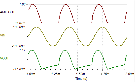
My customer is using the LMC7101 now, the schematic is below. But for some chips, the output is different. The rate is about 2%. I have checked the schematic, it should be ok(the input frequency is 3khz). Could you please help double check the schematic of the LMC7101?
Thanks.
Br
Frank
Frank,
Please attach the schematic again. It is missing from the first post.
In what way is the output different? Do you have waveforms that show the diffrence?
Frank,
It is true that input caps block DC component of input and output caps block DC component of amplifier output.
Nevertheless, Vos matters because the amplifier is not linear; the apparent gain changes with both Vos and input Vpp.
Is the goal to have a nonlinear amplifier that only amplifies part of the input signal?
Frank,
Here are the simulated output(s) as originally designed (3kHz 100mVpeak). See how the outputs are distorted.
Here is the output by adding two more components, one resistor and out capacitor.