 Scheme equipment indicate on attached figure.Questiones:
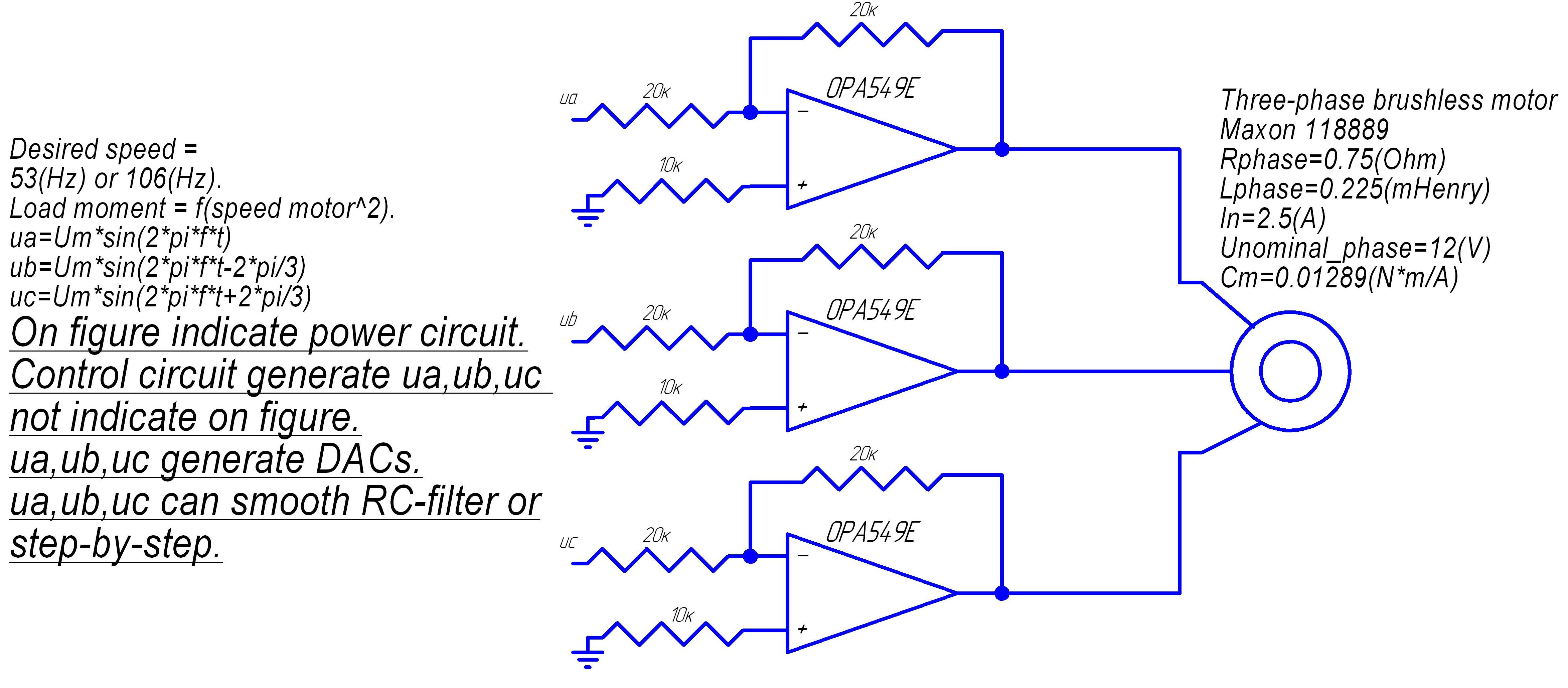
1. What correcting circuit is needed for op amp?
2. What scheme replacement op amp is become for datum equipment?
3. What is dependency Zout op amp of frequency?
4. What scheme op amp is good for datum equipment (noninverting amplifier
or inverting amplifier)?

-
Ask a related question
What is a related question?A related question is a question created from another question. When the related question is created, it will be automatically linked to the original question.