Other Parts Discussed in Thread: TINA-TI, THS4631
Dear TI expert:
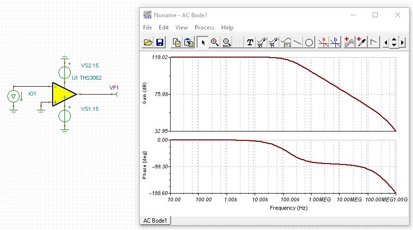
I want to use an analog PI(Proportion-Integration) regulator based on op amp THS3062 in a system. Before this, I try to use this analog PI regulator in a relatively simple circuit as Fig1.

Fig1. Simple applications of PI based on op amp
L1’s voltage is summed with 2V at op amp’s + terminal, whose result is the input of analog PI’s. Obviously, this circuit can control L1’s current to decrease linearly with time at speed -2000A/s, and hence, L1’s voltage should stabilize at -2V. For the analog PI regulator based on op amp in Fig1, the proportion and integration coefficients KP and KI are as follows. The Cc is always set to 10pF.
KP=1+RC2/RC1 KI=1/(RC1*CC)
Firstly, I use a common op amp OP747 instead of THS3063 in the simulations. RC1=RC2=30Ω and KP is set to 2. With OP747’s spice model(downloaded from TI website), L1’s current and voltage is simulated as Fig2 and the control goal is met. When I set RC1=RC2=100Ω, 300Ω or 1kΩ, the simulation results are all as Fig2.
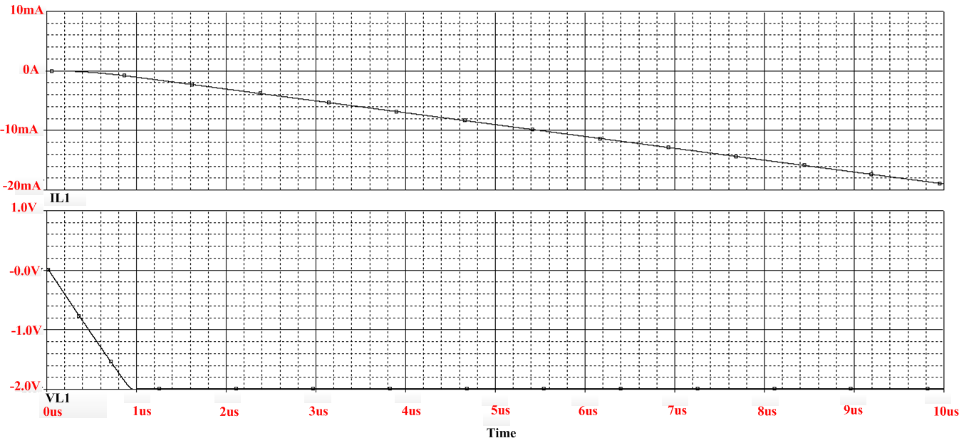
Fig2. OP747 based PI simulations results for L1 current(upper figure) and voltage(lower figure)
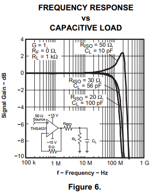
Then, I use the THS3062 based PI regulator in Fig1. Due to the simulations for OP747, KP is also set to 2 here and Cc is always set to 10pF. According to THS3062’s datasheet(Fig.3), when G=2, the recommended feedback resistor value is 560Ω. So RC1=RC2=560Ω is chosen for the analog PI regulator.
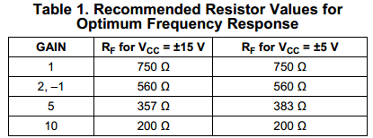
Fig3. THS3062 datasheet for recommended feedback resistor values
Hence, with THS3062’s spice model(downloaded from TI website), L1’s current and voltage simulations are as Fig4. The L1 voltage doesn’t stabilize at -2V, hence the fall speed of L1 current isn’t controlled to be -2000A/s.
Besides, the op amp’s inverting and noninverting terminal’s input current are very large in the range of several mA as Fig5. This is certainly not the correct result.
Then increase RC1=RC2 to 1kΩ, and the simulations of L1 current, L1 voltage, THS3062 inverting noninverting terminal’s input currents(in the range of several hundred nA) are good now.
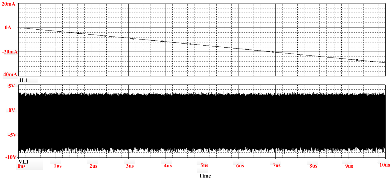
Fig4. THS3062 based PI regulator's simulation results for L1 current(upper figure) and voltage(lower figure)

Fig5. THS3062’s inverting and noninverting terminal’s input current
I have 2 problems:
- In the simple example above, the chosen values of feedback resistor are very different from the datasheet’s recommendations, what about the more complex system? In practical experiments, how to choose the appropriate RC1 RC2 and Cc.
- Why THS3062’s inverting and noninverting terminal has such a big input current(mA when RC1=RC2=560Ω in Fig.5) in this simple simulation? This will worsen the PI regulation. In my more complicated system’s simulations, I encounter a similar problem: In Fig1, the inverting terminal input current is as big as RC1’s current, then the feedback RC branch conducts nearly no current and the PI can then hardly function properly.I wonder why this big current arises and how to solve such a problem.
Best regards!