This thread has been locked.
If you have a related question, please click the "Ask a related question" button in the top right corner. The newly created question will be automatically linked to this question.
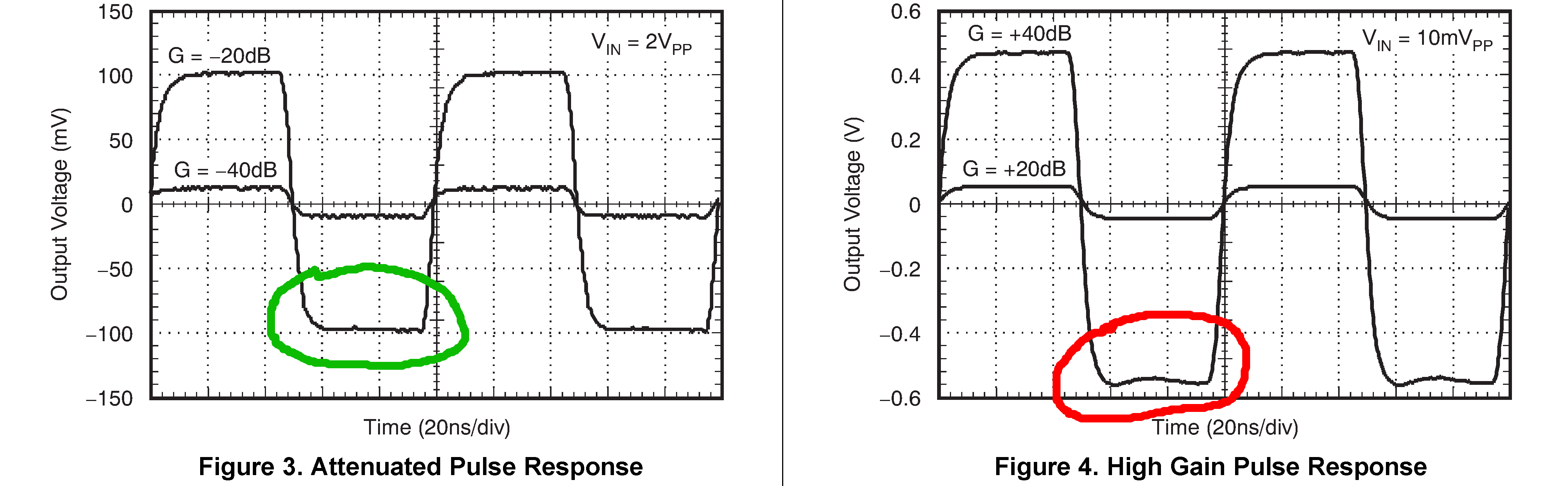
Hello, I have an application where I need to use a VGA but I also need to get a monotonic step response. With "monotonic" I mean that I need first-order responses and avoid overshoots, especially for the falling edge of the input signal. Take for example the VCA810 - which is the best one I've found so far - and look at datasheet's figures 3 and 4 (see image below). For small gains the response is first-order (green circle) but for large gains the response becomes of higher order (red circle). I've noticed that all of the VGAs apparently have this "issue".
My questions are therefore two:
I cannot place a preamplifier before the VGA (and then use smaller gains) because I need to support a very wide input signal range. A possible idea could be to "invert" the input signal so that the falling edges become rising edges, and then invert the signal again after the VGA. But this is a sub-obtimal solution, because I need a clean response also for the rising edges (even if it's less critical).
Any idea is much appreciated.
Thank you!
L.
Thank you, very informative!
Giving it some thoughts, I think that the best solution is to place a unity gain filter before the VGA, and a post-amplifier after the VGA, so that I can limit the gain of the VGA itself below its "cross point" of 20 dB. I cannot use a comparator: even if my input signal is quite similar to square wave (to a pulse, actually: it is a LIDAR application), it is nonetheless an analog signal and it is acquired by an ADC.
This will complicate a little my signal chain, but using low noise/low offset components it should be ok.
I would like to send you a schematic, just to check if you see something wrong and to get an opinion. I'd prefer not to post it in the forum. Can you give me an e-mail?
In the meanwhile, thank you again!
L.
Hi Larry,
My email is s-cashin@ti.com, but can you explain in more detail why you can't accept any negative overshoot?
Best regards,
Sean
Hello Sean, I've sent you the schematic.
I can explain the problem with the overshoot right here, since maybe it could be helpful for someone else. In "classic" LIDAR applications (not the "new" automotive ones) the signal received from the PMT/APD is a pulse where the falling edge is the most critical and important part. A lot of dynamic range is required, since obviously as farther the light pulse goes, as weaker the echo received will be.
In the figure below you can see a typical received pulse (Y axis in volts logarithmic, X axis in ns). The orange trace shows the pulse as it is received, the blue trace shows the pulse after it has passed a VGA, opportunely scaled down to be overlapped with the input pulse. I don't remember the gain set for this experiment, it might be 20 dB or more. This is a VGA that was equipped in a previous version of our equipment (just to name names, it was an Analog Devices' AD8330).
In absolute terms, the overshoot is quite small (around 100 uV referred to input) but it completely disrupts the "tail" of the pulse, where there could be small but importants phenomena to be detected. On the other hand with a first-order response, even if the tail gets distorted, the signal remains monotonic and you still can get useful "spikes" emerging from the tail.
L.