This thread has been locked.

If you have a related question, please click the "Ask a related question" button in the top right corner. The newly created question will be automatically linked to this question.

TINA/Spice/INA333: INA333

Part Number: INA333
Other Parts Discussed in Thread: TINA-TI, , TL431, INA122

Tool/software: TINA-TI or Spice Models

Hi TI:

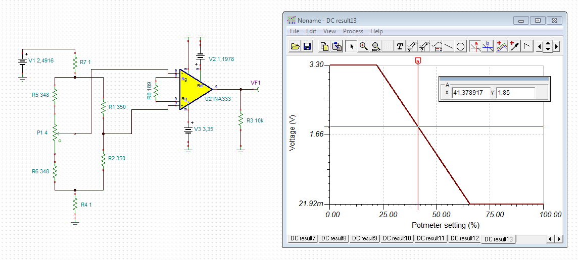
I am new to this blog and have a 'challenge' that I would appreciate some assistance in.  I have been using dual op-amps to amplify a bridge with dual strain gauges for an outdoor application. Currently I amplify by approximately 530x's and then digitize the value using a Teensy 3.2 at approx 100 hz.  I have found that I have some initial drift in values - and then after about 10 minutes - values stabilize. To try and improve stability, I purchased INA333 and have been experimenting with it.  I am struggling - and suspect it is a Common Mode issue.  Thanks to your TINA download - I tried to mimic my circuit and sure enough - I cannot get any readings from TINA!  My strain gauges are 350 ohm and I calculate that they vary by +/- 0.5 ohm for my application.  I use two different voltage supplies one for the bridge and one for the amplifier) - thinking this would increase the stability of my circuit and the noise.

I enclose my TINA export of my model.  The strain gauges are represented by R5 & R6.  I even downloaded your output vs CM model  - to try and get the CM voltage in range - but that does not seem to help.

I would appreciate some assistance in figuring out what I am doing wrong, if the INA333 is the right module for my application and how to configure the circuit.

Thank you

Andy Basacchi, P. Eng.CM INA333 SIMULATION.CIR

  • Hi Andy,

    can you show us a schematic? Or your TINA-TI file? It's a file with the ending ".TSC".

    Kai
  • Hi Kai:

    I thought the file would have been included with the export file.  Here it is.

    Thank you

    Andy Basacchi, P. Eng.CM INA333 simulation.TSC

  • Hi Andy,

    there are several issues with your schematic.

    1. The REF voltage at pin 5 must be provided low omically and not by the help of a voltage divider. Otherwise you will destroy the symmetry of the differential amplifier section and the INA333 can no longer work properly. Figure 32 and 33 of datasheet show how this can be done.

    2. If the input voltage from the sensor is bipolar, your output voltage wants to swing arround the REF voltage. If the supply voltage of INA333 is unipolar (single supply), you should move the REF voltage up enough between the supply rails. If the REF voltage shall be 0V, on the other hand, you should use a bipolar supply voltage.

    3. If the input voltage from the sensor is unipolar, your input voltage should be positive (Vin+ > Vin-). If you use a single supply for the INA333, keep in mind that the output voltage cannot fully go down to 0V. So, either you use a REF voltage > 0V to lift the output voltage a bit, or you can use a (small) negative supply voltage.  

    Kai

  • Hi Kai:

    This is a single battery application, thus my voltage supply is unipolar.  I will change my ref voltage to include the single op-amp and move the Ref voltage so that my output can swing between the ranges I am expecting.

    To your third point, my input voltage is unipolar.  As my strain gauges are going to vary, do I need to ensure that the input voltage (assuming I put the bridge value to Vin+ needs to always exceed the value of Vin- ?  Thus do I need to ensure that for all values of my strain gauge ranges - VIN+ is always greater than Vin-?

    Thank you

    Andy

  • Hi Andy,

    I only wrote this this because in your simulation your input voltage was Vin+ < Vin-. If the input voltage is unipolar and is always Vin+ < Vin-, this might not be what you want... No, you need not to ensure this.

    Kai

  • Hi Kai:

    I added an op-amp to drive the Vref per the data sheet and was able to start to get the model to work. I noticed that the model would not compute a solution when my gain was approaching what I needed (530) and thus was limited to a gain of just over 100. I am thinking for my application with the unipolar voltage and strain gauges I will revert to my previous circuit.

    Thank you for your assistance.

    Andy
  • Hi Andy,

    a gain of factor 530 is possible with the INA333. I have choosen a REF voltage of 400mV and a single supply voltage of 3.4V:

    Kai

  • Hi Kai:

    Thank you for providing me this - as I had given up with the chip.  I have been playing with the model and some of my parameters - and now seems that I can see the linearization.  Do you know if there is a way that I can vary two input parameters at the same time (e.g. R5 and R6 in opposite directions) and plot the output?

    Also how do you actually select the output - as I have tried to insert 'output' and cannot get it to work?

    Thank you

    Andy

  • Hi Andy,

    TINA-TI behaves a bit weird sometimes. Changing some of the components values or the analysis parameters can help then.

    Varying R5 and R6 in the opposite way can be done by using a pot which is stepped through when doing the DC transfer characteristics. I show you how:

    And I forgot to give you the TINA-TI files:

    andy.TSC

    andy1.TSC

    Kai

  • Hi Kai:

    I appreciate you doing this.  I will test out the circuit and let you know how I make out.  Can you tell me why you used the two 1 ohm resistors R4 and R7?

    Thank you

    Andy

  • Hi Andy,

    you introduced R4 and R7 in your original simulation... :-)

    Kai
  • Hi Kia:

    Ok - thanks for reminding me.  I got the circuit working finally thanks to your help. I also got the model working too.  What I noticed is the circuit is very sensitive to initial start up from a cold (non-powered up position).  What I see is the output voltage change from some initial 1.85 volts (my ideal voltage at 50% of the pot) and then it goes down without any adjustment.  I suspect it is the components warming up and thus changing their properties.  Do you have any suggestions to minimize this startup variation?

    I have measured that it takes some 20 minutes for it to stabilize.

    Thank you

    Andy

  • Hi Andy,

    could it be that the strain gauges are heating up because their bridge voltage is too high?

    What strain gauges do you use? Can you give a link to the datasheet?

    Kai
  • Hi Kai:

    I thought the same thing, but in further investigation - I think it may be my voltage reference for the bridge circuit. I use two sets of reference using the TL431.  One produces the 3.35V for the INA333 and the second produces 2.485V for the Bridge.  I did this many months ago to stabilize the circuit when powered by a battery (e.g. 3.7V).  What I am noticing now as I am looking at this very closely, is that the TL431 is probably heating up and per their temp vs ref voltage - the voltage drops as the temp increases (e.g. heating up).  This is then reflected in a changing output voltage.

    The strain gauges I am using are similar to 'LY13 - 6/350' from HBM - https://www.hbm.com/en/4561/ly-linear-strain-gauges-with-1-measurement-grid/

    I am using the aluminum ones- at 350 Ohm.

    Thank you

    Andy

  • Hi Andy,

    can you specifiy the drift? You say it's 1.85V output voltage immediately after the power-up. What is the output voltage 20min later?

    Kai
  • Hi Kai:

    Here are two screen shots of my measurements of the Output voltage over time (minutes) and also the bridge voltage as supplied by a TL431 voltage source.

    As you will see - they both changed and I suspect that the Bridge voltage source impacted the output.  

    Thanks

    Andy

    INA333 Time Test.pdf

  • Hi Andy,

    a shift from 1.85V output voltage to 1.3V within 20min is really huge and absolutely abnormal!

    This huge shift cannot be explained by the shift of bridge voltage from 2.4916V to 2.4906V, because this shift is only 1mV and is transformed by the action of bridge into an even much smaller shift of differential input voltage.

    The first which came into my mind when looking at the measurements was that the bridge seems to be a bit imbalanced. In idle situation with a fully balanced bridge you should see an output voltage which is similar to the REF voltage:

    To simulate the influence of bridge voltage shift I have searched for the pot setting which results in an output voltage of 1.85V:

    Then I have changed the bridge voltage from 2.4916V to 2.4906V:

    It's no surprise to see that the output voltage shifts from 1.85V to only 1.84974V. A simple mental estimation shows the same result.

    No other shift of any parameter of INA333 can explain this huge output voltage shift. You can simply check the performance of the naked INA333 by replacing the strain gauges and R1 and R2 by 0.1% / 25ppm precision resistors. Provided the INA333 isn't damaged you will hardly see such a huge output voltage shift.

    I think you have issues with the strain gauges and eventually R1 and R2. Even if they heat up only a very little, you might see a considerable shift of output voltage. Especially if the bridge is heating up unevenly. Have you glued the strain gauges directly onto a metal surface so that the metal surface can act as a heatsink? Are both strain gauges exactly at the same temperature?

    You use two individual strain gauges right? What, if they are too different and show unequal drifts? Have you thought about using a complete strain gauge bridge where all the strain gauges are made from the same material, instead of using individual strain gauges?

    Kai

  • Sorry, I forgot:

    andy2.TSC

    Kai

  • Hi Kai:

    First I am surprised that you are working on a Saturday - so thank you very much for sending me the note above.  I see what you did and I am pleased to hear that you think there is some imbalance in the circuit.  Let me answer some of the questions and let you know what I am going to do:

    1. As I am testing the INA333 - I did not want to glue the strain gauges and thus not be able to use them again. So I temporarily have them in 'free air' in a  very large enclosure so that it is in a controlled environment.  The enclosure is many times the size of the circuit board - thus it will not overheat within it.  Thus I would say they are at exactly the same temperature as they are within 1 CM in proximity to each other.

    2. Yes I use two individual strain gauges - that are the same (with a few 0.1 ohm).  I use two as I wanted to maximize the strain output by placing them on opposite sides of a small rectangular bar that is bent.  That way they strain in opposite directions - doubling the effective strain and also temperature compensating by placing them on the same side of the bridge (e.g. R5/R6 in your circuit above).  The strain gauges are made from the same material as the bar (aluminum).

    Given your comments - I will now remove the strain gauges and replace them with fixed resistors to test out.  I don't think I have the precision and temp coefficient above but will get the best I have installed and redo the test.  Note that I found that I had to add a 2 Ohm resistor (in series with R6 to ground) to compensate for a variation in R1/R2 in my existing circuit.

    I will let you know what I end up with.

    Thank you

    Andy

  • Hi Andy,

    it's no work. I'm doing this for fun!

    Well, it's expected to have the strain gauges glued onto a metal surface in order to use the metal surface as a heatsink. Having the strain gauges in free air can be the reason for all the trouble...

    Referring to the testing with the "naked" INA333: If the 350R resistors don't heat up, you can take 1% / 50ppm / 0.6W / 0207 metal film resistors. To keep the heat dissipation minimal you could fabricate the 350R resistance by a series circuit of a 200R and a 150R resistor. Do use 1% / 50ppm / 0.6W / 0207 metal film resistors for this series circuit.

    Kai
  • Hi Kai:

    I am glad to see this is fun - as I too see this as a challenge to get this right!  I did further testing with what I had available and please see enclosed PDF for results.

    Test 45: I eliminated the 350 Ohm strain gauges and put in their place 280 Ohm 1% resistors (that is all I had to work with).  As you will see, the result stabilized to a better value but still took time to get to stability.  I noticed the Bridge voltage had quite a bit of randomness - and that it was reducing slightly too over time.  Also after some 140 minutes of observation, I decided to restart my program (did not cycle power) and it automatically adjusts the Ref voltage to give me an output of 1.85v.  You will see the results.

    Test 46:  I decided to eliminate the second separate bridge supply voltage and put a series resistor of approx 135 Ohm with the top of the bridge and supplied from the same voltage that supplies the INA333.  I then ran my test once the circuit had come to room temperature.  You will notice that I similarly dropped in voltage (the output) to a slightly lower value then test 45 - but the Bridge voltage rose this time - and was less random.    I restarted the circuit after 30 minutes - and you will see it is very stable.

    I am now thinking that it will take some 10 minutes for the circuit to come to 'temperature' and then there is minor drift.  I would ideally like that to happen much sooner!

    The next test I am going to attempt is to directly connect the bridge voltage to the same as supplied to the INA333 without my series resistor.

    Love to hear your thoughts on what could be causing this initial drift and what I can do to minimize further.

    Thank you

    AndyTest 45 - 46.pdf

  • Hi Andy,

    I still think that the drift comes from the heat dissipation within the bridge resistors. The current of a usual 350R strain gauge bridge should only be about 1mA. But in your circuit a current of 3.6mA is flowing. So, the heat dissipation is 3.6 ^ 2 = 13 times higher than usual.

    By the way, there's a nice documentation about your application:

    http://www.ti.com/tool/TIPD170

    Kai
  • Hi Kai:

    I will take a look at the article and also at trying to reduce the current through the bridge.

    Thank you!

    Andy

  • Hi Andy,

    I agree with Kai that this is quite a bit of current for a bridge and this may be the source of your issue. Something else that concerns me though is in the data you have posted you call out a reference voltage for each measurement cycle, and the difference in reference voltages correlate fairly well to the difference in your output measurements. By reference voltage, are you talking about the voltage at the reference pin of the INA? What device are you using to generate this reference voltage? If the reference is not stable or the resistors you are using to divide down the supply are too small, it may actually be your reference voltage that is drifting with power dissipation!
  • Hi Zak:

    Once Kai shared his concern for the current through the bridge, I have been looking to modify it down.  I am now limiting the total current to 2 ma - thus 1 ma per side of the bridge.  As I cannot alter the INA333 circuit - as it is soldered in place - I moved to a similar chip I have the INA122 earlier today in a 8 pin DIP.  I have put it on a bread board and now am testing stability using fixed resistors as a start.  I reviewed the Output voltage vs Common Mode application for the INA122 - and got the Vin + and Vin - to be in the mid range of the chart.  In reviewing the data sheet for the sample project for a strain gauge he shared with me, I also noted that my current voltage source (TL431) may be causing significant random noise (as seen in one of the plots of Bridge voltage I shared with Kai earlier).  I am now seriously considering moving away from the TL431 and using the REF5XX 3 terminal series voltage supply for my design.

    Yes my reference voltage is what the chip is seeing in its input.  Per Kai - I stopped using fixed resistors last week as it interfered with the INA333 internal resistors.  What I am using is a 12 bit DAC as supplied by a Teensy 3.6.    The chip allows me to read multiple inputs via it's 16 bit ADC inputs - thus my readings.  I measure the Vref also - and I am finding it is very stable - thus not immediately a source of error.  

    After I configured the INA122 - I did some preliminary measurements and so far looks good.  As my issue is initial warming up of the circuit components - I need to let the circuit reach room temp overnight and then in the morning will test it one more time from a cold start.  I am hopeful that it will give me stable readings that I have been searching for and then will test it with two strain gauges to see temp effect on them.

    If this all works, I will then settle on using the INA333 with the 3 terminal voltage supplies for my circuit.

    I do appreciate the support that TI has been given me to date!

    Andy Basacchi, P. Eng.

  • Hi Zak & Kai:

    I wanted to let you know that I finally got some very good results from my testing of the INA122.  Enclosed you will see the stability plot using strain gauges (350 Ohm) in free air.  The curve is almost dead straight - vs the rising or falling during the initial warm up.  What I did too is to test out the gain of the circuit (see enclosed TINA model of what I had under test) - and now can confirm that I have a delta V output vs Delta R (resistance change) of 2.000 Volts/Ohm. This is what I was targeting as my previsous discreet Op-Amp circuit gave me 1.89 V/Ohm - but was not stable.

    I plan now to use the INA333 with the two REF5XX voltage sources to get further voltage stability - and maintain the same gain.  I have modeled it in TINA (great tool by the way) and am now confident it will work.

    I would like to thank both of you and TI for the support over this past 1 1/2 week!

    Andy Basacchi, P. Eng.

    Final Solution.pdf

  • Looks very good now. Congrats!

    Kai