This thread has been locked.

If you have a related question, please click the "Ask a related question" button in the top right corner. The newly created question will be automatically linked to this question.

TLV6002: output current

Part Number: TLV6002
Other Parts Discussed in Thread: TLV6001, TLV9001, TLV9002

Hi

I have some question about the output current.

#1: The short circuit current is defined on the datasheet as below.


     How much is the Min and Max value? (It might be no data. If it so, how much is the variation we can refer? )

#2: If the output current is exceed that current, what is it happen?  (Actually it is not short circuit current. The current what we are concerned is the output current.)

       In my understanding, the more current will be caused thermal issue. It will be exceed the Abs max rating of Ta if it is continued. Then it is damaged.

       Is my understanding correct?

#3: Does this device have any current protection? 

#4: If it is no current protection and it is damaged, what kind of failure mode is considered?

Best Regards,

Koji Hamamoto

  • Hi Hamamoto-san,

    1. The min and max value aren't given but a good rule of thumb would be +/-20% for device to device variation.

    2. The short circuit current is the maximum output current that the device can provide, it is not possible to force the product to drive more current. It is possible that thermal issues can be created even at values less than the short circuit current depending on the ambient temperature of the device. I recommend watching the TI Precision Labs video on Thermal Stress: training.ti.com/ti-precision-labs-op-amps-power-and-temperature

    3. There is no current protection in this device.

    4. If the device is overheated due to the amount of current and ambient environment, the failure mode will be thermal failure and the device will likely stop working as expected.

    I hope that is clear,
    Paul
  • Hi Paul-san,

    I appreciate your prompt reply.
    We have now some problem that the output voltage goes down if the output current is increased around 15mA. (V+=5V, Voltage follower configuration)

    We think the problem is related the output current. However we are concerned the device has been damaged.

    Best Regards,
    Koji Hamamoto
  • Hi Paul-san,

    I have one more question. Does the output voltage clamp if the output current is overload, ?
    I evaluated with the above condition that is voltage follower configuration and +INB=5V and output current is 10mA. Then the output voltage is clamped at 4V. Is this normal ?

    Best Regards,
    Koji Hamamoto
  • Hi Hamamoto-San,

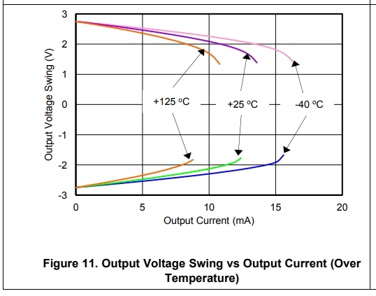
    You're running into the output swing limitation of the op-amp. If you look at Figure 11 in the datasheet, you'll see the "Claw Curves" which describe the output swing versus output voltage. At 10mA output current, the TLV6001 will be limited quite substantially. The case that you are seeing on your board is normal and does not mean the device is damaged.

    For more detail on this topic, I recommend watching these TI Precision Labs Videos: training.ti.com/ti-precision-labs-op-amps

    -Paul
  • Hi Paul-san,

    Thank you so much for your support.
    I understood. That is very helful information (training video).

    On the other hand, Fig 11 is the data at when the RL is connected to Vs/2 and VCM = Vout = Vs/2. (So that ,Vo range is +Vs/2 ~ -Vs/2)

    If it is the voltage follower configuration and RL is connected to GND(Not Vs/2), how can we estimate the output limitation?
    Actually we would like to know how much is the max output current (limit current) when Vin is 3.3V (Vo=3.3V,V+=5V) at the above condition (voltage follower).

    Best Regards,
    Koji Hamamoto
  • Hi Hamamoto-san,

    The claw curves show the maximum output voltage for a given output current that the device can produce, so if you're using it in a topology that is not dual supply, the easiest way to estimate is to simply take your output current and see how much the voltage drops from the rail in the claw curve chart.

    For example, if your output current is 15mA, the claw curve shows that the output voltage will be about 1.75V with ±2.75V supplies, which is a 1V drop. If you were using a single 5V supply and had an output current of 15mA, you would similarly expect a 1V drop, meaning that the maximum output voltage the op-amp could produce would be 4V.

    In the case you gave above, with a 3.3V input with a single 5V supply, my guess is that the op-amp would have to be producing about 17mA of output current before your output would be limited. However, we always recommend operating INSIDE the claw curves. These lines are non-linear regions of operation for the op-amp and you may not get the desired performance.

    If you would like to look at a device with better output drive current, I recommend the TLV9001 - it is a pin-to-pin replacement device that is newer and has better device specifications all around.

    Best,
    Paul

  • Hi Paul-san,

    I am sorry for the delay in my response.

    The following graph is not dual supply. This is single supply but the middle supply of output is Vs/2=2.5V. Is that correct?

    If it is a single supply and the middle supply of output is not supplied,  the above graph can be shown only the output is from the supply rail until 2.5V.

    How much is the max current when the output is lower than 2.5V?

    (I understand TLV9002 is can be replaced.But the customer need to understand this issue.)

    Best Regards,

    Koji Hamamoto

  • Hi Hamamoto-san,

    The image you attached didn't load, can you try again? 

    -Paul

  • The image I posted is Fig 11.

    Best Regards,

    Koji Hamamoto

  • Hi Hamamoto-san,

    My apologies but I don't quite understand what you are asking:

    "The following graph is not dual supply. This is single supply but the middle supply of output is Vs/2=2.5V. Is that correct?"
    --> Figure 11 is dual supply, +/-2.75V.

    "If it is a single supply and the middle supply of output is not supplied, the above graph can be shown only the output is from the supply rail until 2.5V. How much is the max current when the output is lower than 2.5V?"
    --> I don't understand.

    Thank you,
    Paul
  • Hi Paul-san,

    What I would like to ask is how much is the max output current if the output voltage at Vs=5V is 2V or 1V . (Fig 11 is only shown when the voltage drop from supply rail is until 3V.)

    At Fig 11, it is not dual supply. Vs is 5V (Single supply) but VCM=VOUT=Vs/2.

    Please see the condition.

    Please let me know if you have any question.

    Best Regards,

    Koji Hamamoto

  • Hi Hamamoto-san,

    Figure 11 should probably have a note which indicates that the op-amp is being used with ±2.75V supply rails. You can tell that we are using dual supplies because at 0mA output current, you see a max voltage of 2.75V and a min voltage of -2.75V.

    Also it is important to note that Vs = VCC - VEE, so Vs=5 means that the supply voltages are ±2.5V for most of the charts in the datasheet.

    I can't answer your question about maximum output current when the output is 1V or 2V unless I know the load size. But in general, for single supply op-amp operation, you're only going to be sinking or sourcing current, not both, so I doubt that you'll run into any limitation with a 1V or 2V output unless you've got more than 15mA of output current.

    -Paul
  • Hi Paul-san,

    I understood the supply voltage at this data is +/-2.75V dual supply.

    Can I ask one more question?
    How much is the variation of the output current we can use for the estimation? 10%? or 20%?

    Best Regards,
    Koji Hamamoto
  • Hi Hamamoto-san,

    For absolute max current (short circuit current limit, Isc) there can be around 20-30% variation. For the claw curves, there might be slight variation in what voltage the part clamps to for a given output current, but this variation will be quite small.

    Best,
    Paul