This thread has been locked.

If you have a related question, please click the "Ask a related question" button in the top right corner. The newly created question will be automatically linked to this question.

LMV344: Find an alternative operational amplifier “ LMV344 ” for the 28377 Reference voltage source input.

Part Number: LMV344
Other Parts Discussed in Thread: OPA4350, OPA4353, OPA325, TINA-TI

I used LMV344 to build the following circuit as a buffer for the 28377 reference voltage source, replacing the control CARD reference design OPA4350EA. The circuit produced dozens of sets without problems until recently, when new batches of devices were used, the problems were exposed.

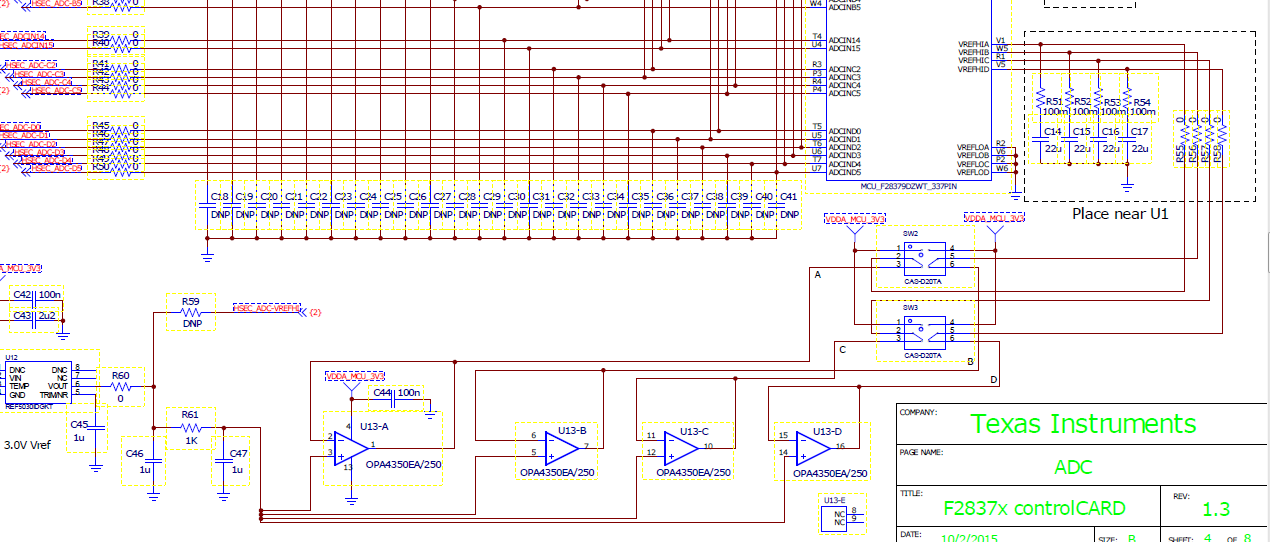
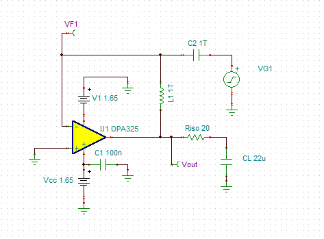
The following is my own schematic diagram.

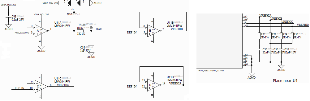
I think there are two problems with my circuit diagram.

1.LMV344 input is not rail to rail.NOT in to V+.SO The input voltage should not be 3V.

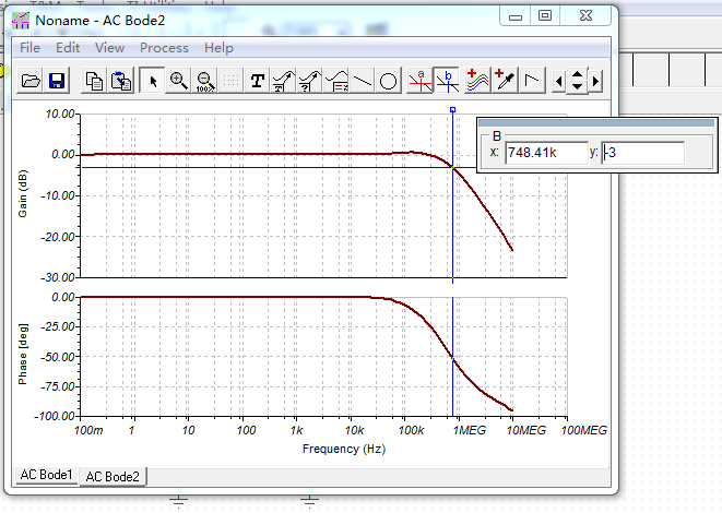
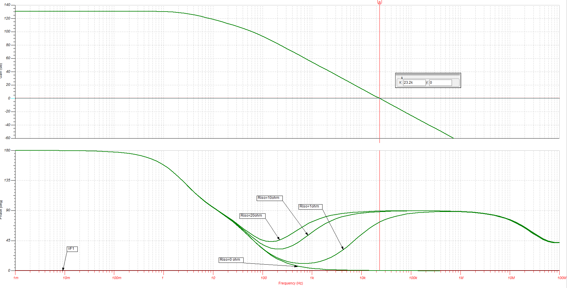
2.Output can not drive so large capacitive load.

I urgently need your help.Answer me the following questions.

1.Which  parameters is the operational amplifier's, we can know LMV344 CAN NOT IN to V+?

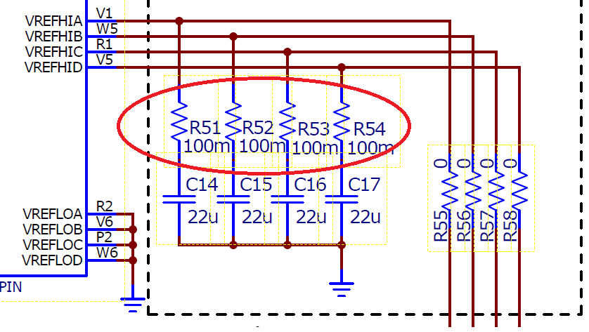
2.Which  parameters is the operational amplifier's parameters, we can know  LMV344 CAN drive how much Capacitance VALUE and we can know   how much resistance VALUE (R51)is need  between capacitor and op amp output pins(R51~R54)?

3.Can you recommend a chip that is fully compatible (pin to pin)with LMV344 to realize the function of the VREF circuit? It would be better if you could tell me the resistance VALUE between the output pins and capacitors.

Thank you for looking forward to your reply.

  • Tina,

    The parameter that specifies the linear input voltage range is the Input Common-mode Voltage range and in case of LMV344 the range is from negative rail to 1V below positive rail.  This means that on 3.3V single supply, the input range is from 0V to 2.3V

    A Small-signal overshoot vs Capacitive load describes the drive capability - ideally, you are looking for overshoot of less than 25%.  You may simulate the overshoot by applying a small 10mV square signal and looking at the output overshoot.

    One part that can directly drive tens uF load is the part you replaced - OPA4350.  What was the reason for that?  If cost was an issue, there is an untrimmed version -OPA4353 - that should have no problem driving your cap loads.

    For more detailed info on stability, please read the stability section in our on-line training material:

  • Thank you for your prompt reply. The operational amplifier that has been used is the lmv344 package, which is TSSOP14. OPA4350 and OPA4353 are not pin to pin. Is there an other recommendation?
  • LMV344 and OPA4353 also come in SO-14 package and there is no other than OPAx350/x353 op amp in PRAMPS porfolio that can drive directly (without help of series output resistor) tens of uF loads. But if you must have TSSOP14 package, you will have to use a series output resistor to drive 22uF load. Since LMV344 and OPA4350 are vestly different op amps, 1MHz vs 38MHz, respectively, we need to know what circuit configuration do you use and what are the most important specs in your application: is it bandwidth, noise, RRIO, IQ, dc precision or something else?

  • Thank you for your timely reply.I really want to know these two questions:

    1、Which parameter of the operational amplifier determines that it can drive uF capacitive load?

    2、 If the output is to be series resistors, how is the resistance value determined? Is the resistance value determined by stability analysisin by Bode Plot?Is this the only requirement to calculate the resistance value?

  • Tina,

    You're trying to get a simple answer to a complex question.  First, circuit stability is a function of circuit configuration - thus, a different configuration will require a different solution.  Second, instability of circuit  while driving capacitive load is caused by a second pole (first pole comes from inside the op amp Miller cap) created by interaction of open-loop output impedance and cap load within the effective bandwidth of the circuit configuration (that's why configuration matters).

    A series output resistor outside the op amp closed-loop creates with CL canceling zero, which stabilizes the circuit. In short, you must choose a series output resistor which will result in a phase margin at the effective bandwidth frequency of your circuit configuration of at least 45 degrees.  Unfortunately, there is no maco-model for LMV344 so I can't conduct stability analysis for you and you haven't provide me with any details on required op amp other than being able to driving 22uF and come in TSSOP-14 package.  For more, please read the stability section under the link I previously included in this post - it answers all the questions you keep asking about. Here it is again: 

  • Tina,

    I have picked OPA325 to show you how to conduct stability analysis - see below.  For buffer configuation, you should use circuit below for the analysis.

    Running AC sweep for different values of Riso, you will notice that it takes at least 20 ohm to assure a minimum of 45 degrees of phase margin - see below.

    I have also attached in this post Tina-TI schematic of the circuit so you may use it for your own simulations.

    OPA325 stability.TSC