This thread has been locked.

If you have a related question, please click the "Ask a related question" button in the top right corner. The newly created question will be automatically linked to this question.

TLC075: Peak to Peak output voltage vs frequency

Part Number: TLC075

Hi,

I have a question related to Peak to Peak output voltage vs frequency in the TLC75 datasheet :

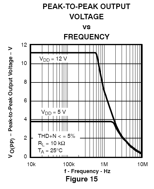
In this curve, how is guaranted the THD+N <= 5%? Is it only on the flat region of the curve?

Could anyone tell me what circuit is used for this test (amplifier with a gain of 10 or more?).

Thanks

Matthieu

  • Hello Matthieu,

    This graph does not provide information for a guaranteed specification it is only a typical specification graph.

    The THD+N <= 5% would be for the entire curve not just the flat region.

    The circuit configuration is likely an inverting configuration to prevent the common mode voltage from changing. I do not know the gain of the circuit but I would image that changing the gain would have minimal effects on THD since the limit is 5%.

    Thank you,

    Tim Claycomb

  • Matthieu,

    The gain would likely be 10 or less. The limiting factor for the flat area is based on VOL and VOH of the op amp. The curved area is limited by the op amp's slew rate. The gain bandwidth product will not be the limiting factor for this chart.
  • Hi Ron & Tim,

    Thanks for your answer.
    So, if the THD+N is less than 5% for all frequency (even in the curved part of the curve), how this test is performed?

    I assumed that we just put a sine in input and sweep it. But in this case the output at 10Khz and 5Mhz for example will not have the same THD+N.

    Thanks
    Matthieu
  • Hi Matthieu,

    I do not know exactly how this graph is generated but the way that I would try to replicate the graph is by setting an output voltage amplitude and sweeping the frequency (or vice versa). The THD+N of the amplifier would need to be measured with a limit set to stop and record the THD+N measurement once it is at ~5%. I would increase the frequency using a binary search approach to increase the speed of the measurement.

    A piece of equipment called the Audio Precision 2700 (and possibly other Audio Precision models) has ability to increase the input amplitude until a desired output voltage amplitude is achieved. There may be a way to set an input amplitude and have the piece of equipment adjust the frequency until a desired THD+N level is achieved. But I am not sure if this is possible to do on this piece of equipment.

    As Ron mentioned in his post a gain of 10 or less was likely used. Even a gain of 10 might prevent the amplifier from going into slew rate limit. A gain of -1V/V (noise gain of 2V/V) was most likely used. Please see out videos on Bandwidth for more information.

    Thank you,

    Tim Claycomb

  • Matthieu,

    I have seen this type of test before. It works something like this and takes at least 4 hours to run.

    LET last used input amplitude = VCC/GAIN
      FOR every frequency (low to high)
        try last used input amplitude 
        DO {
    record output on oscilloscope run math of capture waveform to check distortion % if distortion less than 5% THEN EXIT DO lower input signal } save frequency and last output amplitude in chart NEXT

  • Thanks a lot Ron and Tim, it's very clear now.

    Matthieu