This thread has been locked.

If you have a related question, please click the "Ask a related question" button in the top right corner. The newly created question will be automatically linked to this question.

VFC320: f/V-Converter, supply-voltage confusion

Part Number: VFC320

Page 2 (f/V-Converter): Rated Voltage: +-15V, Range +-13V to +-20V

Page 3 (Absolute Maximum Ratings): Supply Voltage +-20V and now comes the confusing part for me: -Input … +- Vcc and +Input … +- Vcc

I hope this means the supply-Voltage equals +-Vcc, because that’s what I did.

Page 8: In fig.9 on pin 4 is -Vcc, pin 12 is + Vcc. The cermet potentiometer R5 needs +15V and -15V which are the same as the supply voltage in this case, or do I need the +-20V as listed on p.3

My chosen components for F_FS = 200kHz, D_FS = 0.25 are:

C1= 150pF; NP0 ceramic 1% tolerance
C2 = 1nF; ceramic 5% tolerance
C3 = 1nF; ceramic 5% tolerance
C_bypass = 100nF; ceramic (instead of 10nF)

R1+R3 = 40kOhm; 33kOhm metal film 1% tolerance and 10kOhm cermet potentiometer
R4= 10MOhm; +-10% carbon film
R5= 50kOhm; cermet potentiometer, 75ppm/°C
R6 = 12kOhm; carbon film
R7 = 2,2kOhm; carbon film

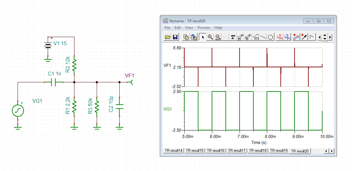
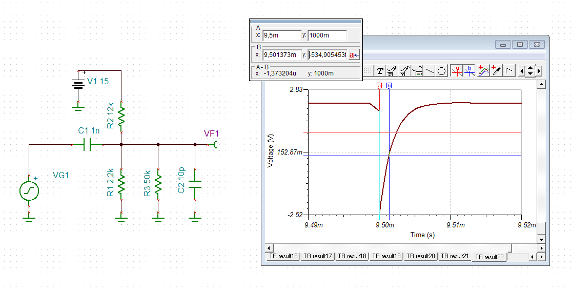
Since my +-Vcc is +-15V in my case, I connected +-15V to R5 and pin12/pin4. I tested with a square-wave-signal with +5V and F_FS = 50 Hz to 200kHz but I do not get any kind of response. Any ideas or did I misinterpret something wrong?

Thanks for the help and my thesis also thanks you for the help.

  • Hi Lauritz,

    the absolute maximum ratings on page 3 just mean that the input voltages "-in" and "+in" must not exceed the supply voltages.

    Regarding figure 9: The cermet trimmer's terminals (R5) should be connected to the same potentials as +Vcc and -Vcc of VFC320, which is +15V and -15V here.

    I would increase C1 a bit. 300pF might be better suited.

    The input circuitry C3, R6 and R7 is designed to interface a TTL-signal! Its idea is to differentiate the edge of square wave to very narrow pulses and to produce one negative going pulse of about 1.0...1.5µs length per period, as shown in this simulation:

    And with zoom:

    So, it's important that the square wave input signal has enough amplitude and is fast enough. If the rise and fall times of edges are too high, the differentiating will not work.

    lauritz.TSC

    You should also have a look into this very interesting application note:

    www.ti.com/.../sbva005

    Kai

  • Lauritz

    We haven't heard back from you so we assume this answered your questions. If not just post another reply below.

    Thanks
    Dennis
  • After various testing this resolved every Problem. Thank you for this detailed and fast reply.