This thread has been locked.
If you have a related question, please click the "Ask a related question" button in the top right corner. The newly created question will be automatically linked to this question.
Hi,
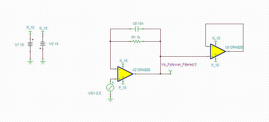
I'd need to drive the input of the OPA828 with a sharp square signal (from 10 K and up to 1 MHz); I need to add a capacitor in the feedback loop to compensate for the pole introduced by the feedback resistor.
So, what is the input capacitance of the OPA828 since it is not mentioned in the datasheet?
Also, I need to use it as a buffer for the same square input. So, documentation of the LM6172 is suggesting to place in the feedback a resistor of 1K and a capacitor too of 2pF.
What would be the case for the OPA828?
Tanks
Hi Jean,
The OPA828's input capacitance is 2pF differential, 9pF common-mode, as specified in "Input Impedance" on page 5 of the datasheet. There is a SPICE model (both for PSpice and for TINA-TI) available for the OPA828 which models the device's input impedance, slew rate, and other parameters. I'd recommend building your circuit in simulation first and getting it tuned for the step response you're looking for. This will also allow you to troubleshoot any effects of loading on the output of the OPA828.
Hi both,
Thank you so much for your great support. I was confused by the values mentioned in page 5; it is now clear to me.
I have also downloaded and tested the TINA model of the OPA828. As you'll see it in the attached file, the OPA828 as a follower without a resistor and capacitor feedback seems just fine with a 0-5 V square signal; I'm not sure how in reality it would do.
I've also done the same follower, but this time with the resistor and capacitor in the feedback. I've tried capacitor values from 5pF, and it seems that a 10nF ( !) capacitor is the best one. I'm dubious of a so large feedback capacitor and would like to ask how much should I trust this value since I'm using many times this circuit.
The 3rd circuit shows a variable gain montage, with the feedback capacitor being 15pF now; much more expected value.
So, why this difference between these two values?
Thank you so much so far for your great help.
Best,
Jean
Hi, Thanks.
I'll in such case let my compensation in place, and will decide upon test to leave them or unsold them; this is easier having to had them if they are needed.
Thanks for your feedback concerning simulation vs. reality; I'm been for long now using simulation, breadboard and PCB; indeed, I could see that there are differences. I usually check the global functioning with simulation, breadboard for timing and actual PCB for final implementation and tweak.
As mentioned in the message below, the 9pF is to model the fact my circuits will driving another input of an OPA828; I'm not driving a cable or a capacitor, but purely a resistor on another OPA828 input.
Still, the 10nF in the feedback path is surprising, and I was wondering if anybody has ever implemented the follower with the feedback resistor and capacitor as shown in my file.
Best,
Jean
Hi Jean,
Thanks for clarifying on the load capacitance.
I think I have an explanation for why such a large capacitor is required across the feedback resistor in the buffer case. To begin, I started from your TINA schematic, but replaced the fixed load capacitor with an additional OPA828 instance, as shown. In some cases (especially op amps with anti-parallel diodes between their inputs) this can help to catch unusual transient behaviors early in a design.
The feedback loop for U2 in this circuit can be redrawn as:
This gives rise to the following feedback equation:
With a zero set by the feedback resistor and feedback capacitor, and a pole set by the feedback resistor and combined feedback and input capacitance.
With no feedback capacitor, we get a first-order pole around 14MHz with no zero.
I built a stability test circuit for this in TINA:
Running an AC simulation gives the following curves:
One guideline we use for stability is rate of closure between 1/B (reciprocal of feedback gain) and the amplifier’s loaded open loop gain (Aol). A 20dB/decade rate of closure is typically stable while a 40dB/decade rate of closure is typically unstable.
In this case, Aol decreases at approximately -20dB per decade while 1/B begins to slope upwards at ~14MHz (eventually reaching to a slope of +20dB/decade). By inspection, this gives a rate of closure somewhere near 40dB/decade, which is likely to be marginally stable at best. This is also confirmed by the phase margin of ~13 degrees.
Adding increasing amounts of feedback capacitance begins to decrease the rate of closure by shifting the pole frequency lower and adding a zero above it, as can be seen in the plot for the same circuit with a 10pF feedback capacitor:
With 10pF, the rate of closure is now closer to 20dB/decade, with an increase in phase margin to 59.29 degrees.
As feedback capacitance becomes larger and larger, it increasingly dominates over the Cin term, and the equation for B to reduces to:
or approximately an all-pass filter characteristic.
This same effect can be created by simply decreasing Rf (In fact, a simulation of the AC stability of the pure buffer case showed no concerns).
I suspect that remaining overshoot in this circuit may be caused by the OPA828’s slew boost circuitry, or by other higher-order effects inside the amplifier itself, as the overshoot does not exhibit the typical ringing behavior expected from a second-order system. If slew boost is responsible, simply slowing down the input signal's rise time slightly may eliminate this artifact.
Looking at a noninverting amplifier case, we can re-draw the feedback network as
With feedback described as
This is, again, a pole-zero pair. In this case, however, the pole frequency is determined by the parallel combination of Rf and Rin interacting with the parallel combination of Cf and Cin.
Substituting Rin = Rf, we find:
If we set Cf = Cin, we get B=1/2 (independent of frequency), giving us an all-pass characteristic as above.
For the noninverting amplifier circuit, the input resistors R3 and R4 interact with the input capacitance of the OPA828 as well, forming a low pass filter which slows down the input slew rate, helping eliminate the overshoot seen in the buffer configurations.
Hi Alex,
What a beautiful reply: learning from such an expert is a great experience. I went on to look at the "TI Precision Labs - Op Amps: Stability", which was a great refresher but as well I learned a load of new stuff.
I know have a very good understanding of your reply; I have figured out why you added the Cin of 11pF at AIoB.
The only point missing to my understanding is the very large C1 and L1 at the input of the stability analysis; in the videos I watched they introduced them but still did not explain why.
Could you tell why they are needed, please?
Once again, I was delighted to read your reply; I've learned so much!!!!
Best,
Hi Jean,
C1 and L1 interact with the original components of circuit and introduce unwanted times constants and corner frequencies. To make them stay outside the analyzed frequency response, they are choosen as high as possible.
Referring to your question:
"Still, the 10nF in the feedback path is surprising, and I was wondering if anybody has ever implemented the follower with the feedback resistor and capacitor as shown in my file."
Having such a high phase lead capacitance is not unusual. I use a circuit with a 100nF capacitance. :-)
Kai
Hi Kai,
Thank you so much; everything is now clear, and I can conduct my own AC analysis in TINA.
Thank you for your reply related to the value of the capacitance; I'm now reassured.
Fantastic support, and impressive expertise from TI's guys!
Best,