This thread has been locked.
If you have a related question, please click the "Ask a related question" button in the top right corner. The newly created question will be automatically linked to this question.
To hom it may concern
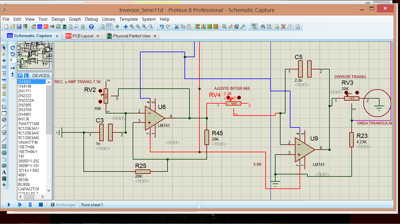
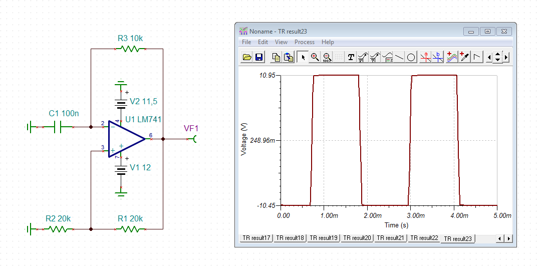
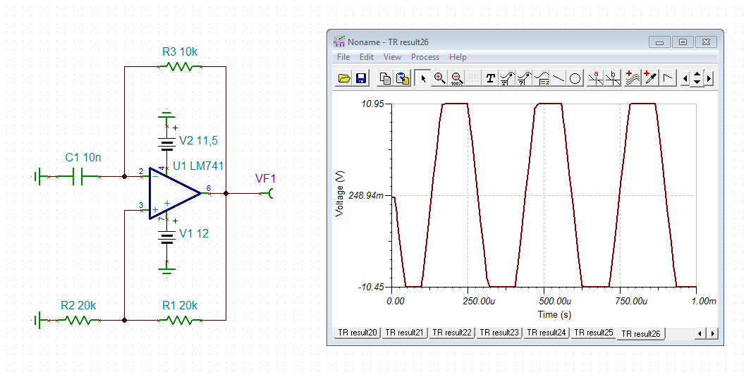
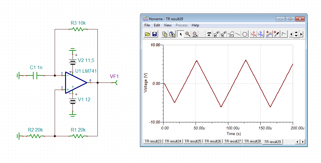
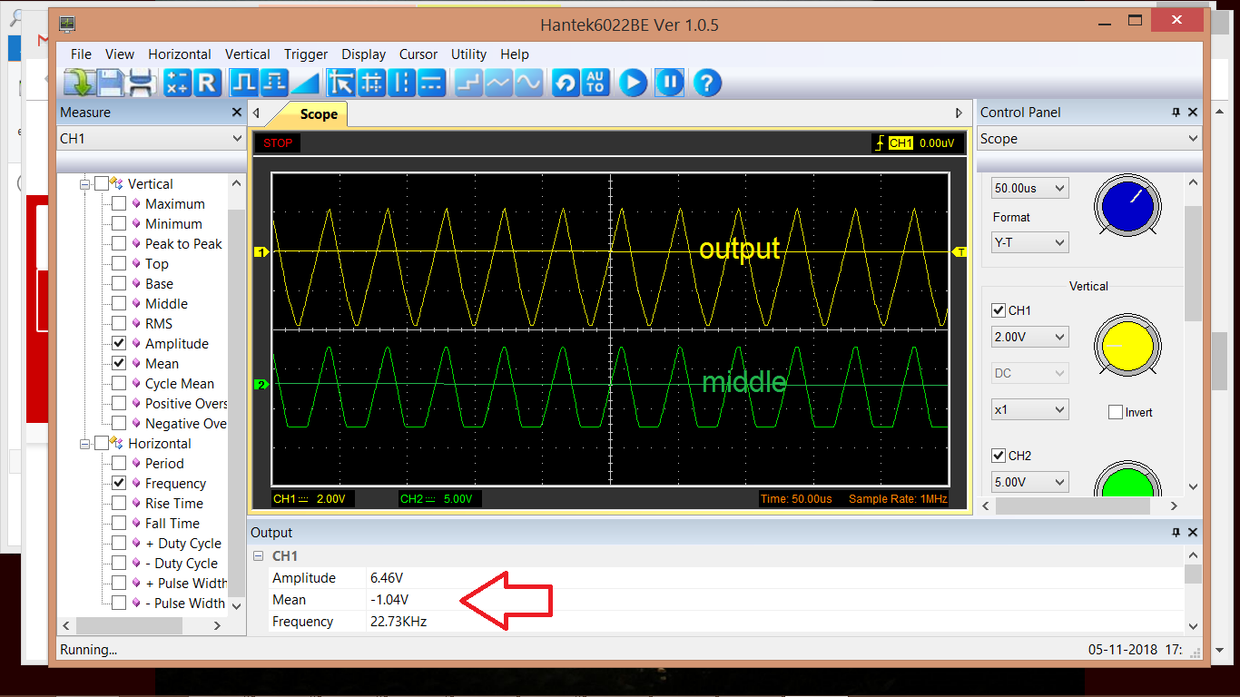
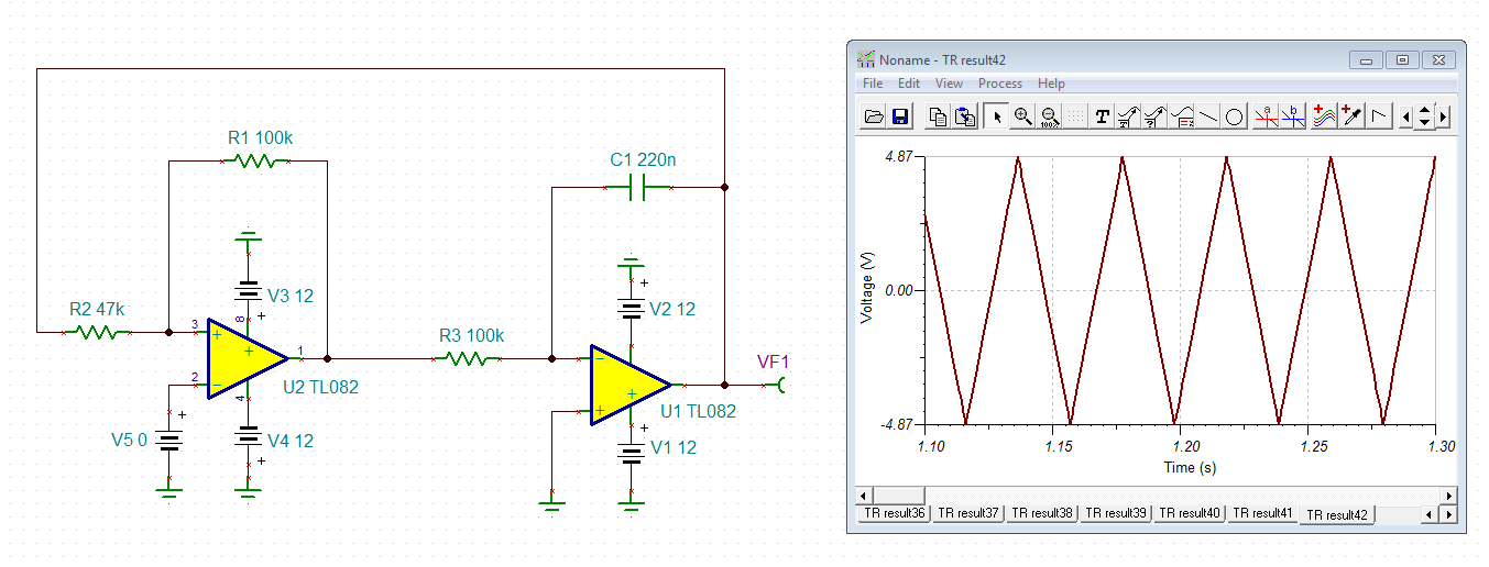
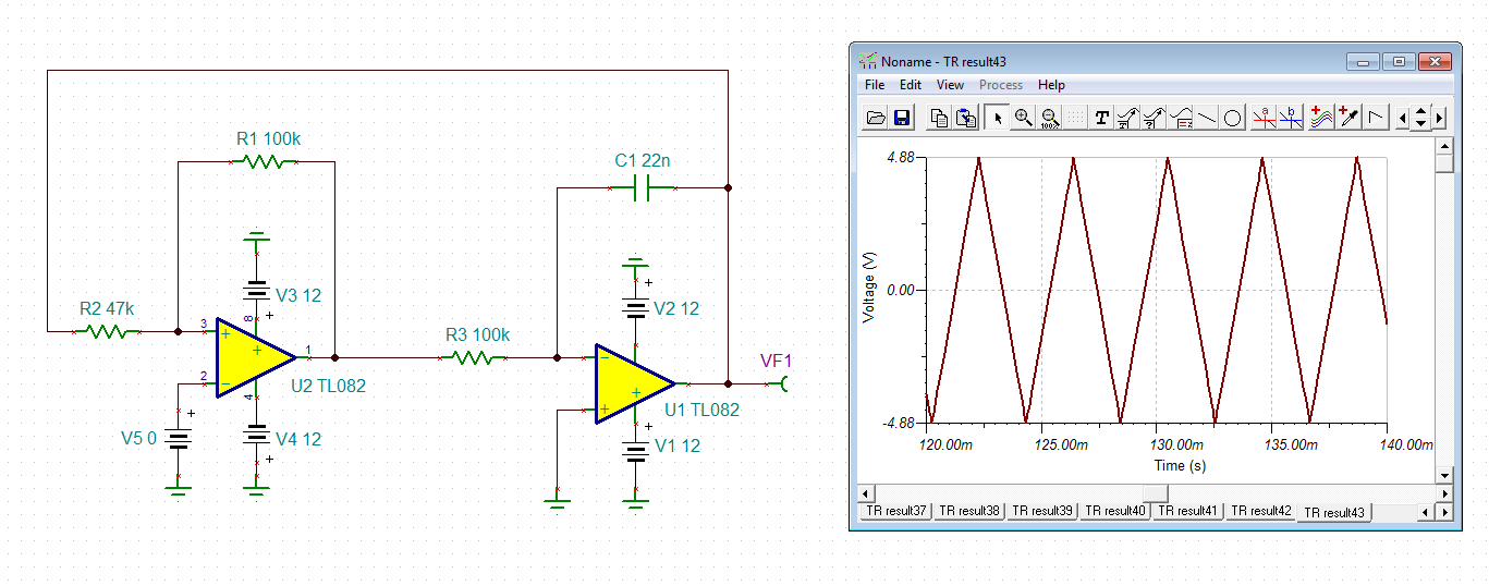
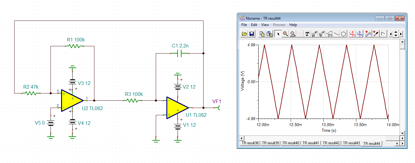
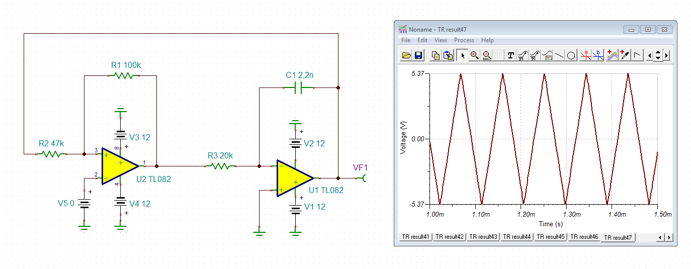
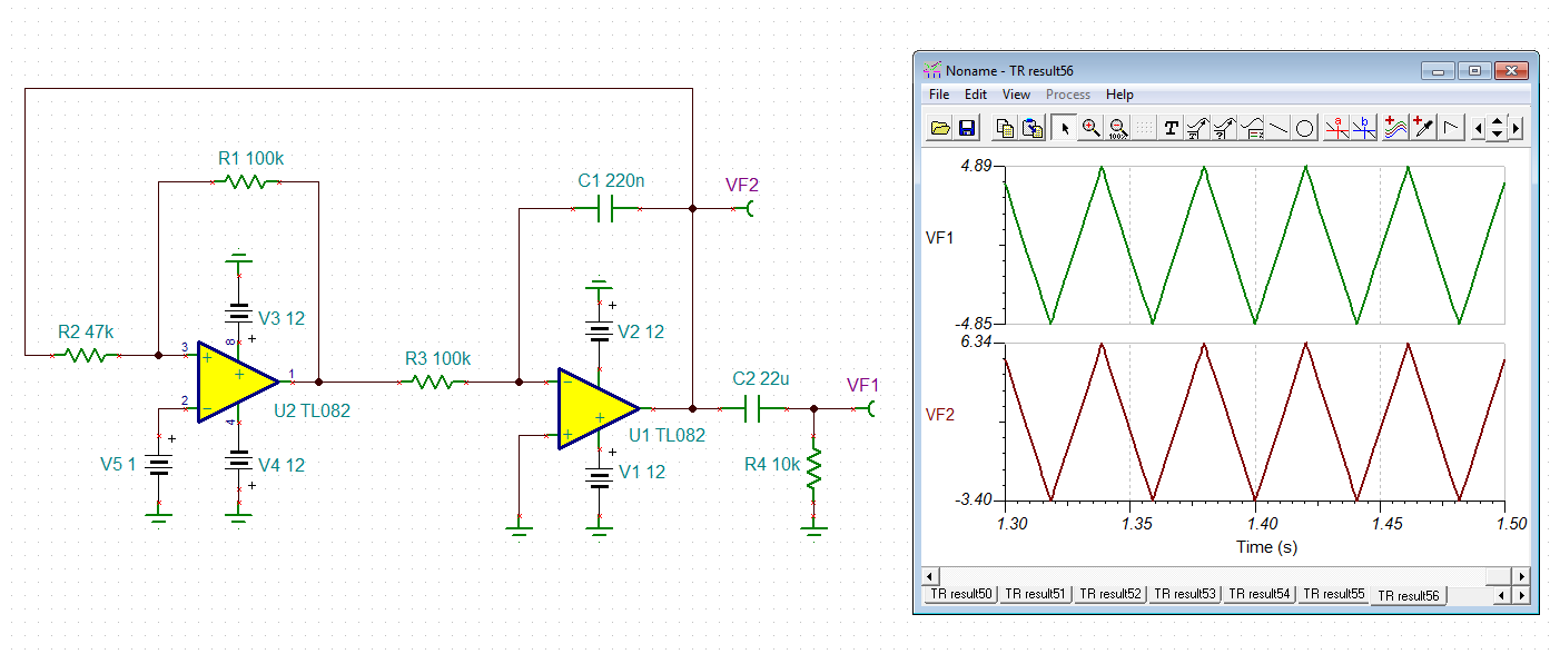
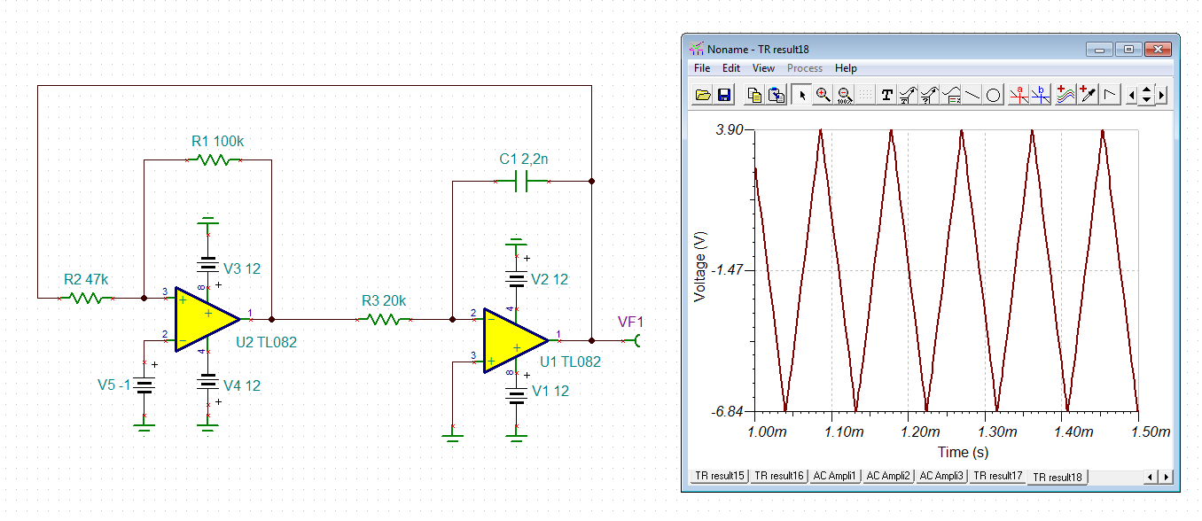
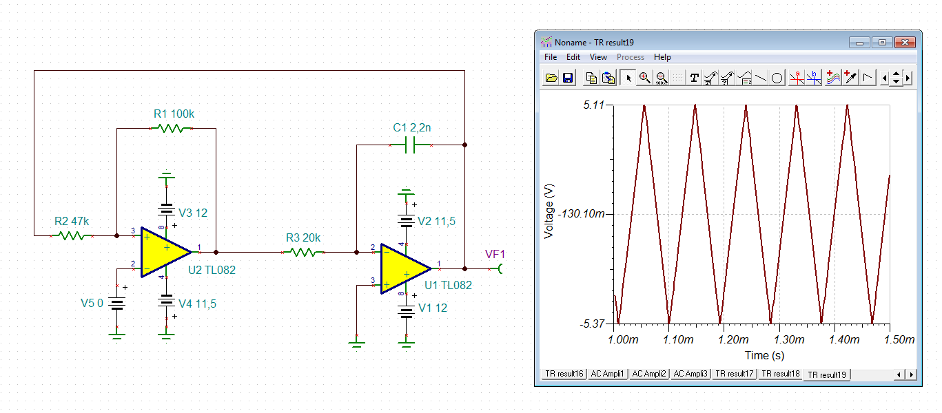
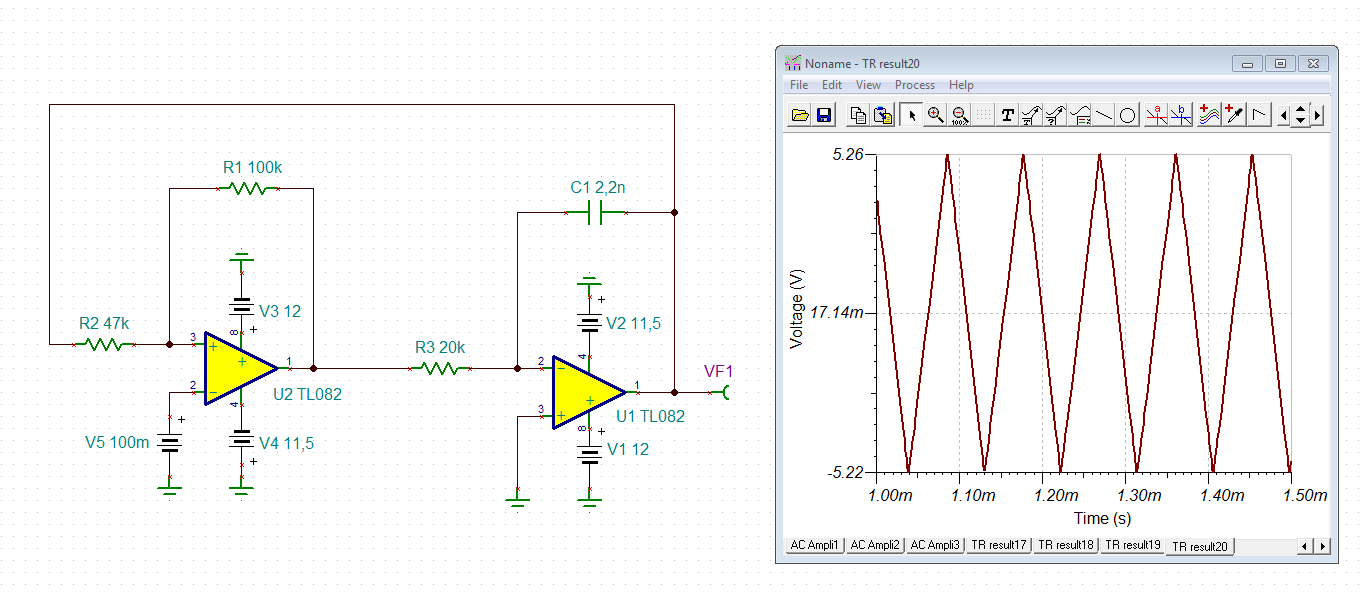
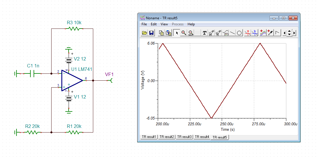
I'm using two LM741 to make a triangle signal, but the signal is umbalanced respect zero. Positive part is 1.8 V and negative part is 2.8 V in the output of the first ampop and simmilar to the output of the second. I rode about 1,5 pins offset balance, but as I understand it is just to balance feeding. I'm using a PC's power supply where I get 12 V and -11.5 V. The feeding balance is opposite of what I'm getting. What do you suggest to do to get a balanced output (simmilar positive and negative parts of the signal) respect zero?
Thank you for your valuable time
Luis
Hello Luis,
What are your values for VDD and VSS? [Edit: I assume VDD is 12 V and VSS is -11.5 V. Is this correct?]
What are you expecting to see at the output? What is the amplitude of the desired triangular waveform? What does your output look like right now?
Also, it seems your input signal is a triangular wave. Is this correct? What is the amplitude and shape of your input?
Regards,
Daniel
Hi Luis,
the left side of your circuit shall be a square wave oscillator? It would work properly with a much bigger time constant RV2 x C3:
But if you decrease the time constant RV2 x C3, the sqare wave becomes more and more a triangle wave because the limited rise and fall time of LM741 begin to flatten the edges:
And with C3=1n, finally, the square wave has gone and looks like a triangle wave with decreased amplitude:
So, the LM741 is not fast enough to generate a square wave. It's slew rate is too small.
There are two remedies: 1. You take a faster OPAmp to generate the square wave, or 2. you use another methode to generate the triangle wave.
A triangle wave of what frequency do you want to generate?
Kai
The yellow signal in the image has a much shorter positive part, so I use it later in a logic gate but this positive part doesn't reach the logic 1, which I need to do. The input to the first opamp is a sinus signal made by the rc oscillator. The output of first is something as a triangle and the last output (yellow) is the one I need to balance.
Luis,
I believe there are two parts to your circuit. The first part of your circuit generates square wave and second part of the circuit is an integrator. As you can see the square wave is not square wave (you are hitting slew limitation) and the area below and above the ground is not equal. If you integrate this wave you will have not have triangle wave that is equal below and above the GND (Middle). Two solutions 1) Slow down your square wave and make it look like a square wave that is equal on both sides. 2) Use amplifier that has higher slew rate if you need high frequency triangle wave.
Sanjeev
Hi Luis,
the triangle is unbalanced because the slew rates of the rise and fall of output signal are slightly different. For the LM741's output it's harder to rise than to fall. That's the reason why the the triangle is unbalanced.
Again, what signal do you want to generate?
Kai
A triangle signal, as balanced respect zero as possible. How could I 'up' the signal? I though that maybe unbalancing feeding, so, diminishing voltage feeding on minus pin, with a resistive divider, or pulling up the 12 V to something betwen this and 18 V, but maybe somebody with experience on this amplifiers could have a simpler solution. I don't know if moving feeding as described can solve my problem, but maybe somone has done it this way and know that it is a solution. What do all of you think?
Hi Luis,
I would do it this way:
By the help of V5, which is 0V here, you can shift the triangle wave up and down a bit, if desired.
Another method to make the triangle wave balanced is to use a highpass filter at the output:
But the highpass filter needs some time to settle.
Kai
I noted the feedback trough a 47 K resistance. I'll make some tests. So to shift down output I'd need to feed V5 with a lower than zero voltaje? Would it work to shift it in the original circuit?
Hi Luis,
in my last simulation I have set V5=1V. This shifts up the triangle wave. A negative V5 would shift it down:
Please notice that I have taken a supply voltage of +/-12V. When using an unbalanced supply voltage you might need V5 to recover the balance of output signal, like shown in this example:
But I would not use an unbalanced supply voltage, because this will make the triangle become asymmetrical, as shown in this example:
It's best to have a well regulated and stable bipolar supply voltage which is balanced. Take care, PC supply voltages can be very noisy and full of ripple. I wouldn't use them for this circuit.
In your original circuit the triangle wave is unbalanced because the LM741 shows different slew rates for the rise and the fall of output voltage. The LM741 is totally overstrained in this circuit and will not show a stable performance. Slew rates depend on several factors like temperature, etc. . So, you might need to adjust the shifting all the time when using this circuit. And the frequency will not be stable either. I wouldn't use your original circuit.
Kai
Thank you very much for your advices, I'll make some tests.
I'd like to know which are the 'overstrain' conditions in a lm741.
Hi Luis,
by "overstrained" I mean that the LM741 is much too slow for this circuit. Have a look at your original circuit again: U6 is actually meant as a square wave oscillator. With a proper chosen OPAmp, which is fast enough, the output signal of U6 would look like this:
You can see that the output signal is a square wave. But now see what the LM741 is doing in the same circuit:
The edges are so slow that the output signal looks like a triangle wave and not a square wave as it should. So, the LM741 is much much too slow for this circuit.
For such a square wave oscillator an OPAmp with a high slew rate must be chosen. The LM741 has a slew rate of 0.5V/µs. But the TL082 has a slew rate of 13V/µs. So, the TL082 is 26 times faster!
Kai
It says that my account (new) is not ellegible for samples, and if I want to know why to do click in a link, which is not available.
If you know what are the requisites for it, I'll consider TI components for the design. Indeed, I have a provider in China for printed circuit boards, I'd like them to build the complete circuit, but I suppose then you would provide them. Have you a dealer in China?