This thread has been locked.
If you have a related question, please click the "Ask a related question" button in the top right corner. The newly created question will be automatically linked to this question.
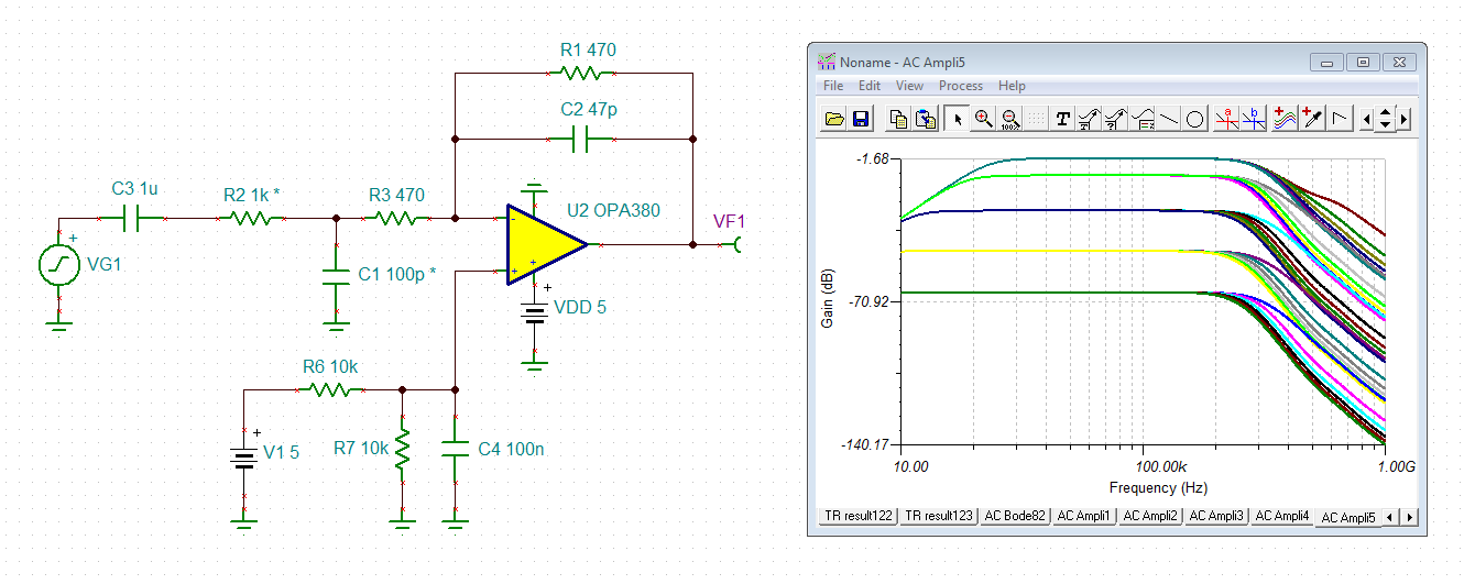
I setup the circuit above with OPA380.
Is this circuit correct? If correct Vout need to be -500mV, right?
I read near by -500mV with 1000 ohM but for example if I change it with 22 ohM, I didn't get the 5V (its 20V but the upper limit is 5V) or I didn't get -50mV with 20K resistor.
Where is the problem?
This is my test setup. Later I will change the 1000 ohm resistor with 2 platin metal electrode (in salty water) and change the +5V input signal with a bipolar square wave.
I need help to understan TIA configuration, thanks.
Hi Ismail,
the OPA380 cannot withstand such a high supply voltage. +/-5V is too high. Please read the datasheet.
Kai
Hi Ismail,
A transimpedance amplifier (TIA) is meant to convert a small current signal into a larger voltage signal. Typically, a current signal is connected directly to the inverting input of the amplifier. Since the inverting input is high impedance, all of this current must flow through the feedback (or TIA gain) resistor. Since the amplifier will hold the inverting input equal to the non inverting input voltage, which is 2.5V in this case, the Vout = (Vin+) - Isig * Rf = 2.5V - 1mA * 100V/A = -2.400mV
Your test setup above is an inverting amplifier, with a gain of Rf/Rg = 100/1000 = 0.1V/V. If you change the resistor values, you will get different voltage gains. However, in a TIA with a current input, the Feedback resistor (R1) alone sets the transimpedance gain.
Best regards,
Sean
Hi Ismail,
your circuit can become unstable, if stray capacitance is present at the -input of OPA380 or if R2 is very high. So, I would make the following changes:
R3 isolates the input from stray capacitances. C2 additionally improves the phase margin. The simulation assumes stray capacitances of up to 120pF and measuring resistances of 100R to 1M.
I would use a measuring frequency of up to 100kHz. The signal should optimally be a sine wave, or at least a square wave without steep edges.
C3 helps to prevent polarization processes at the electrodes which can be observed when DC voltages are present between the electrodes. Even small DC voltages can totally ruin such a measurement.
Use very short but shielded (!) cables to go to the measuring resistance.
Kai
There was no problem, The circuit gave you different outputs for different resistor values because that changed the current input.