This thread has been locked.

If you have a related question, please click the "Ask a related question" button in the top right corner. The newly created question will be automatically linked to this question.

THS7001: I want to replace LMC6482 with PGA which one is Best THS7001 or PGA11x

Part Number: THS7001
Other Parts Discussed in Thread: LMC6482, PGA113,

Hello TI,

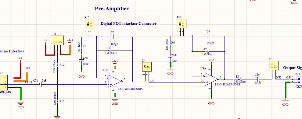
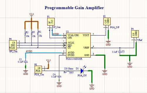
I want to replace LMC6482 with PGA  for Sensitivity adjustment

i already tested both PGA(THS7001 and PGA113) with my exiting Circuit, we not getting any solid solution for our application 

PGA113 follow the Preamplifre Output, I attach Output pic of PGA and LMC6482 preamplifire output 
1.when i connect Input to channel one CH1 there is no any Output 
2.there we try to test on CH0, there is output but PGA Output Follow the LMC6482  preamplifire output there is no any variation even i change gain of the PGA ....?


3.I don't understand what is the issue, anyone can help to resolve this issue 

 THS7001 Preamplifire part not working but when i try to test PGA part of THS7001 there is also some unaccepted output 
1. Input supply voltage of THS7001 is +5V
2.VTH +5V and VTL 0 but output swing between 0 to 3v3 ..?
3. when i try to change Gain of THS7001 there no any Variation ....? 
4.For the THS7001 i follow the THS7001 EVM Schematic 

  • Hello,

    Looking at your schematic for the PGA113, I see that your AVDD pin and DVDD pins are connected to ground through a capacitor? Is that correct or is there some power supply on them that I don't see? Secondly are you sure that that your SPI communication is correctly changing the gain on the PGA113?

    It also looks like you have provided me with the schematic of the EVM instead of your own schematic. I want to see your schematic so that I can see what you are doing.
    What do you mean by Vth an Vtl? Do you mean the clamp voltages? The clamp voltages don't drive the output, they are just there to protect any overshoot and undershoot.

    Thanks!
    -Karan

  • Hello Karan,

    AVDD and DVDD pins are connected to pin1 and pin10 before that there is filtering capacitor
    by using logic analyzer we crosscheck the SPI output and it is set properly

    VTH and VTL is clamping voltage, But it not protecting Undershoot and Overshoot when we Observe output on CRO
  • Hi Rahul,

    it's very very difficult (read impossible) to decipher the schematic of pre-amplifier. At the output of pre-amplifier, is there a 10µF cap? At the input of PGA113, is there a resistor to GND?

    Kai
  • Hello Kai,

    output of pre-amplifier there is 10uF cap and at the input of PGA113 there is 0.1uf cap for filtering and current limiting resistor for LED

    You have any reference schematic, where i can verify my schematic by that

    1.In THS7001 i need to use both Pre-amplifier and PGA, is it possible ...?
    2.what i need to set SHDN pin, when want to use Pre-amplifier and PGA both..?
    3.as per my observation, only work at a time Pre-amplifire or PGA..?
    4.In my application, i use both Pre- amplifier and PGA

    can you provide any application circuit of THS7001 for reference, which help me to resolve my issues

    Thanks for your valuable response