This thread has been locked.

If you have a related question, please click the "Ask a related question" button in the top right corner. The newly created question will be automatically linked to this question.

LMH2832: LMH2832 SPI readback problem

Part Number: LMH2832

Hi,

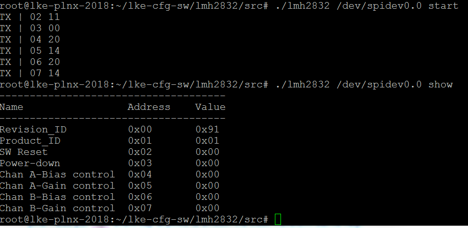
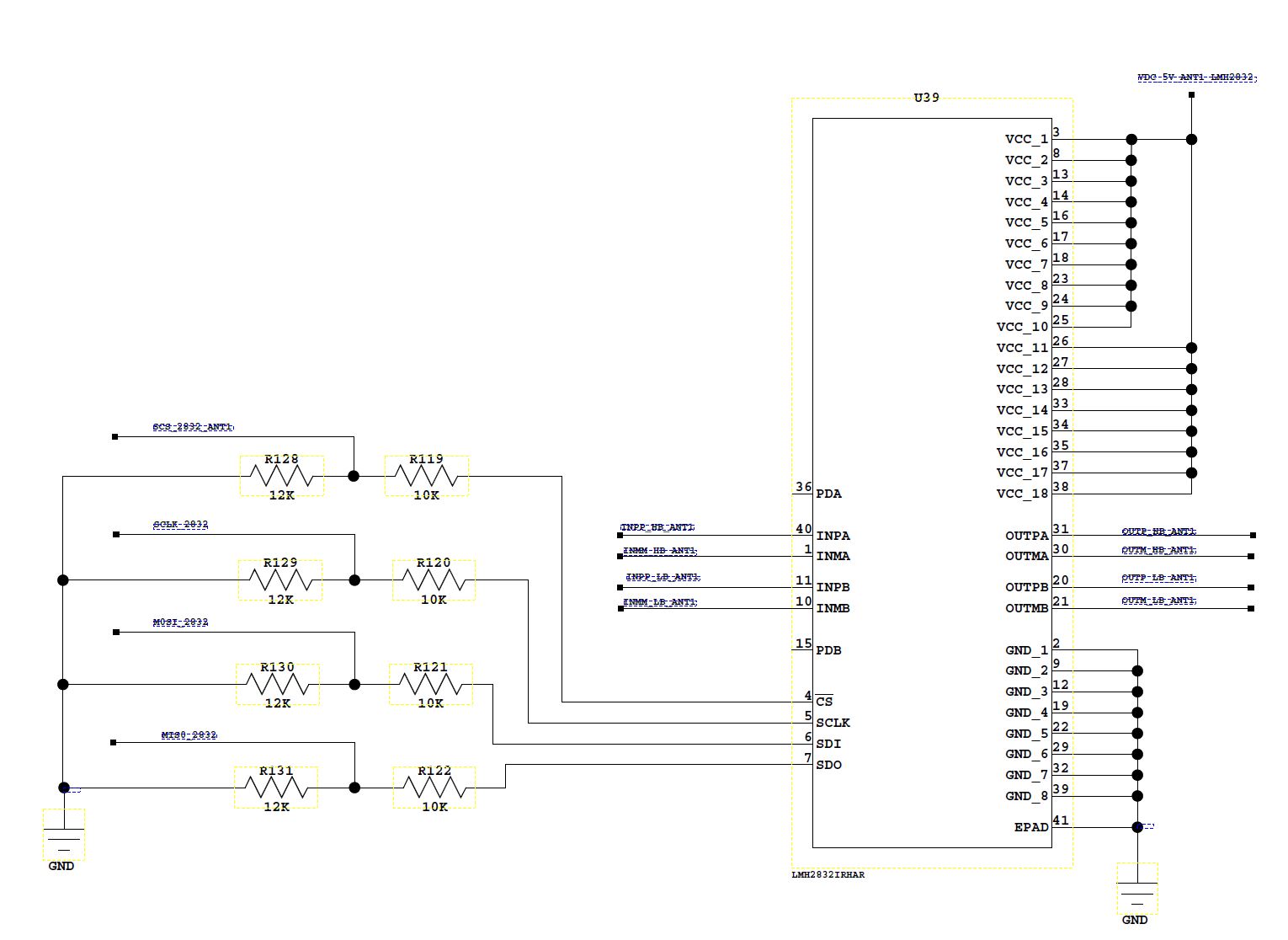
I have used LMH2832 to my system board and I could control gains successfully via SPI control. But somehow I could not readback the SPI register value. I put 500 ohm in series to pin# 4,5,6,7 which are SPI related pins. I also put 10pF shunt cap at pin#5 to smooth the clock waveform but no help. Revision ID and product ID seems to have some value but rest of them is all "00". can you please help me how to readback the right value from SPI? FYI, I have attached screen shot that SPI program and readback routine shown below.

Thanks

  • Hello Youngho,

    Can you share your schematic? Is the values read from the addresses consistent or do you continuously get different results?

    Best,
    Hasan Babiker
  • Hi Hassan,

    Yes, I read very consistently the same value. Here Is the schematic screen shot at LMH2832 but some modification.

    R119, R120, R121 and R122 were replaced with 500ohm resistor.

    R129 was replaced with 10pF cap.

    R128, R130 and R131 were removed.

    FYI, these SPI signal is going to TB1 board via P1 connector (as attached in PDF file). This signal is then interfaced with ZCU102 FPGA. Since ZCU102 can take 3.3V line rather than 1.8V, I had to put voltage translator (SN74AVC4T245PWR) in between. I have set this up 3.3V --> 1.8V from ZCU102 to LMH2832 and 1.8V --> 3.3V from LMH2832 SDO pin to ZCU102.

    In short, ZCU102 <--> TB1 <--> Mezzanine board that has LMH2832.

    we set clock speed as "SLOW" in ZCU102, and I think this will be 25MHz but need to check.

    TB1_rev3_012319.pdf

  • Hello Youngho,

    Could you also share the waveforms for the SPI pins when trying to read the registers?

    Best,
    Hasan Babiker
  • I can't take a picture for waveform in the lab for the security reason but I found data has near the half cycle delay compared with 12.5MHz clock causing the read with different value to what it supposed to be. I think this delay might caused by long cable (~16") and transmission line from ZCU102 FPGA board to the LMH2832 chip. I plan to slow down the clock speed such as 1MHz to see if this delay or slippage can be improved. If you have better idea, please let me know.

    Thanks

  • Hello Youngho,

    Let me know if slowing down the speed helps fix this issue. Just to be sure, is the FPGA board outputting a high bit for the first clock cycle on the SDI pin to trigger a read?

    Best,
    Hasan Babiker
  • I have changed series resistors to 10ohm and removed all shunt resistors then it worked out without slowing down the clock.
    Thanks!