This thread has been locked.

If you have a related question, please click the "Ask a related question" button in the top right corner. The newly created question will be automatically linked to this question.

LM2907-N: LM2907-N for 50Hz 60Hz detect

Part Number: LM2907-N
Other Parts Discussed in Thread: LM2917-N, OPT101, LM2903

Hi Team,

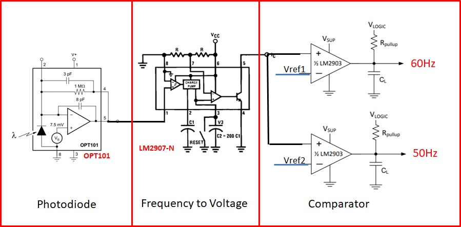
my customer is looking for 50Hz/60Hz detector for Fluorescent lamp flicker detection, I make proposal below and would like to check if LM2907-N is the right solution propose to customer? thanks 

Eddie Chou

  • Hi Eddie,

    I've tried to determine what each stage is doing in the schematic, and I am not totally sure what you had in mind regarding their operation. Can you describe your expectations of their operation, with and without light flicker, and what each stage's output will be in each case?

    See TI Application Note AN-162 for more information about LM2907-N/LM2917-N applications:

    www.ti.com/.../snaa088.pdf

    Regards, Thomas
    Precision Amplifiers Applications Engineering
  • Hi Thomas,
    Customer would like design a stand-alone module to detect whither Fluorescent lamp flicker frequency is 50Hz or 60Hz.
    We propose OPT101 as photodiode solution and LM2907-N to detect the frequency. customer just would like provide I/O pin to detect whither Fluorescent lamp flicker frequency is 50Hz or 60Hz.
    Is the block we provide suitable for this application?

    Thanks & Regards
    Eddie
  • Hi Eddie,

    Here are my thoughts on your circuit:

    If the light applied to the photodiode flickers at either 50 or 60 Hz, the dc voltage level will momentarily drop from the ambient level. It would appear that the OPT101 output would be a constant level with occasional downward spikes when the flicker occurs. The output would need to be characterized so that you know exactly what you have to work with when driving the LM2907-N frequency to voltage converter.

    I am not sure how you are attempting to use the LM2907-N in the 100 pulse counter configuration. Applications Note AN-162 states on Pg. 12, "Figure 19 shows a circuit which will count up a hundred input pulses and then switch on the output stage. Examples of this application can be found in automated packaging operations or in line printers. The output of the tachometer is proportional to the product of supply voltage, input frequency, a capacitor and a resistor. Any one of these may be used as the input variable or they may be used in combination to produce multiplication." I would need your explanation of the way the LM2907-N is being applied before I could say if this is a viable option.

    The LM2907-N in the 8-pin package requires the pulse applied to pin 1 have transitions that drop below 0 V for the comparator to switch. So as shown that will not work since the OPT101 output will not drop below 0 V. If the 14-pin LM2907-N is applied the pin 11 comparator input can be biased one diode up from ground as shown in datasheet Figures 20 through 22. Pin 1 would still be the input that the OPT101 would drive.

    The LM2907 pin 5 output does not appear to be connected correctly. The output transistor's collector is connected directly to the non-inverting inputs of the LM2903 comparators. It would appear that an output pull-up resistor would be required at pin 5.

    Assuming the LM2907-N can produce two distinctly different output voltage levels then the window comparator outputs could be used to indicate when 50 or 60 Hz flicker is present.

    I do think that this circuit needs to be carefully analyzed and proven functional before suggesting its use.

    Regards, Thomas
    Precision Amplifiers Applications Engineering
  • Hi Eddie,

    when driving the fluorescent lamp with 50Hz mains voltage the flickering will be 100Hz because each half wave will produce light.

    Kai
  • Eddie

    We have not heard back from you so we will close this thread. Please reply if further discussion is needed.

    Thanks
    Dennis