Hi,
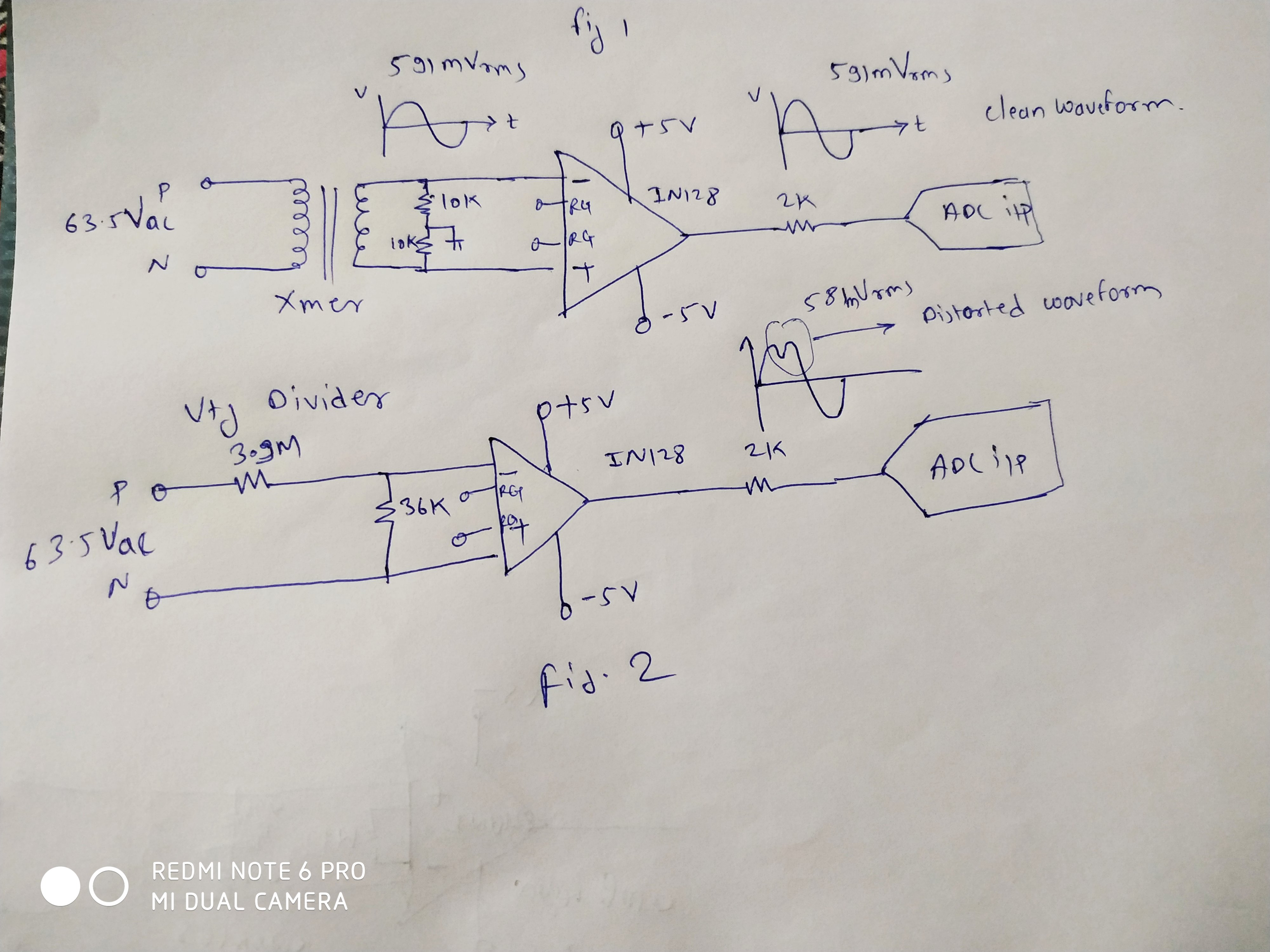
I am using INA128 for mains AC voltage measurement. I am using two different circuits on is using isolation transformer and other one is using Resistor voltage divider. In case of voltage transformer input voltage is 63.5vrms and output of transformer is 591mV RMS. This 591 mVrms is given to INA128 amplifier with gain is one. INA input pin is terminated to ground using 10K resistor. In this case of circuit I get clean, non distorted output from INA128
In second circuit concept I have used resistor voltage divider to down convert high input voltage to low 591 vrna voltage.
Using 3.9M ohm and 36 K ohm resistor. And this low voltage is given to INA128. In this case I get distorted output in positive half of sine wave. It looks like saturated at positive peak or harmonics of 2nd 3rd order even if input voltage is very low 591mvrms as compared to supply voltage +5 and -5volt.
Please suggest correct method to interface voltage divider to INA128 to remove distortion
Thanks and regards
Swaminath