This thread has been locked.

If you have a related question, please click the "Ask a related question" button in the top right corner. The newly created question will be automatically linked to this question.

LMV762Q-Q1: biasing voltage

Part Number: LMV762Q-Q1
Other Parts Discussed in Thread: LMV762, , ISO7721, ISO7720-Q1

Hai,

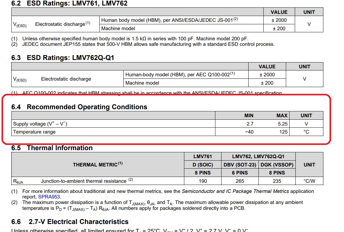
  I have a doubt regarding the biasing supply voltage of LMV762 comparator. Whether we can apply negative biasing voltage for this comparator? In the datasheet ,they have given V+ - V- as max 5.5
V and also give +5 and GND for all the diagrams Please clarify my query.

  • Hello Girish,

    The LMV762Q-Q1 can be used in both single supply (GND and 5V) and split supply (+2.5 and -2.5V).

    As long as the difference between V- and V+ is no more than +5.5V, and V- is the most negative voltage, then it can be used as split supply.

    The applied input voltage must be between V- and 1.3V below V+, or 0 to 3.7V on a 0 and 5V single supply, or -2.5V to +1.2V on a +2.5/-2.5 split supply system.

    Keep in mind that the output swings "Low" to V- and not "GND" in a split supply system.

  • Hai Paul Grohe,

       Thanks for your clarification on the matter. Subjected to this query,please see the attached SiC Mosfet gate driver design of TI.

    TI Designs: TIDA-01605 Automotive Dual-Channel, SiC MOSFET Gate Driver Reference Design With Two-Level Turnoff Protection

    (Note: The actual web link cannot be copied here)

    In the driver design,there is a feature called two-level turn-off given by TI.( See below the screen shot )

    The screenshot of the two level turn-off circuitry is shown above where you can see U8A and U8B comparators LMV762 with +Vcc at +5V and -Vcc at -4V..So V+-V- is coming at 9V which is contradictory to the datasheet values

    Also in the same design the comparator output is given to digital isolator ISO7721 . In case ,when the output of comparator clamps to -4V,the isolator does not have any provision to address this negative voltage .

    The max Vin referred in the datasheet is limited to -0.5 to Vcc+0.5.

    Please refer screenshot below.

    Kindly look into the TI design refer to Fig.6 shown above.

    Highlights: 

    Queries on 

    *  Negative biasing voltage for LMV762-Q1

    *  Negative VIN voltage for ISO7720-Q1

    Thanks....

  • Agreed and we have notified owner of the Design. Closing since continued on another thread.
    Chuck