This thread has been locked.

If you have a related question, please click the "Ask a related question" button in the top right corner. The newly created question will be automatically linked to this question.

LMC662: High temperature opamp (> 200 Deg C) to replace LMC662

Part Number: LMC662
Other Parts Discussed in Thread: OPA211-HT, OPA820-HT, OPA2333-HT, THS4521-HT, LMC660, LMP7721, OPA2333, TINA-TI

Hi !!

Need Help to select  high temperature opamp having temperature rating  >200Deg C as replacement for LMC662

Requirement:

1 ) Need part with Input Resistance > 1T ohm

2) operating Temperature > 200Deg C

2) all other parameters equal or better than LMC662

Regards

  • Hi Kiran,

    have you thought about using forced cooling for the LMC662?

    Kai

  • Hi Mr Kai,

    Greetings !! and Thanks for the reply

    Using forced cooling for my application will complicate the system requirement . So, want to avoid it.

    The critical requirement of my circuit is high input resistance (>1 T ohm). Single channel opamp is fine.

    Can I use OPA211-HT as replacement? and how to read the input resistance compared with LMC662?

    Regards
  • Hi Kiran,

    I think the input resistance of OPA211-HT is very much lower than 1T. See the common-mode input impedance specification in the datasheet of OPA211-HT.

    Kai
  • Hi  Kai,

    Thanks for the reply!!!

    Yes, I did read the specifications.I'm not sure if 1Gohm is enough for my application. I have a high impedance input.

    Is there any method other than forced air cooling to protect the opamp from high temperature like, thermal barrier coating?

    Can you suggest any other opamp with high input resistance (>1 T ohm ) and temperature >125 Deg C

    Regards

  • Hi Kiran,

    an employee of TI might want to suggest you a suited OPAmp. I only want to point out, that it will be very hard to guarantee an input resistance of >1T at elevated temperatures above 125°C. This has to do with the tendency of input leakage currents and input bias currents to drastically increase with rising temperature.

    Kai

  • Kiran,

    There are only four >200C op amps per my search. OPA820-HT, THS4521-HT, OPA211-HT, OPA2333-HT
    At 200C you will find the integrated circuit ESD current and even printed circuit leakage will be quite high.

    OPA211-HT is bipolar input so it's input current is high at any temperature.
    OPA2333-HT may be a better choice, but it is low supply voltage and slower.

    Your best bet is to pick the closest (or any) device of the four I mentioned and start a new post. The engineers that reply will have a lot of experience at 200C. I do not have this experience.
  • Hi Kiran

    The LMC660 is one of the lowest bias current devices - at least the cheapest for the bias current to cost ratio. Any of the LMC6xxx devices will have femtoamps range bias currents at room.

    At room temp, the LMC662 bias current will be below 20fA in the DIP package, and that's on a bad day. As Kai said, the lowest bias currents are near the center of the input common mode range where the ESD leakages cancel. The "sweet spot" will vary per device (in a stable environment, the input pin will eventually "float" to this point).

    CMOS amplifier bias currents double every 10°C, so going from 25C to 205C is a 180°C change. So 10fA becomes 2.62nA

    That is assuming a straight linear relationship. In reality, there is usually an inflection that kicks in at higher temps as other internal leakages start to creep in (usually around 130-140C). I have not taken the LMC series as high as 200C - so I can't say exactly what will happen up there.

    And as Ron said, the PCB materials also start to contribute to leakage. Guarding or "air wiring" may be needed. In the "Good Ole' Days", TO-5 metal can versions were used and the leads were air-wired to avoid PCB leakages (at least for the input circuit section). You can do a similar thing with the DIP package by bending the input lead in the air (as shown in the LMC660 datasheet). SMT devices tend to have higher leakages due to the closer pin spacings and surface resistivity of the PCB (and difficulty running guard traces between pins). SOIC is about the smallest you want to go.

    One device that may be interesting, if it does not fall apart, is the LMP7721. It uses a bootstrapped/guarded ESD structure, so the room temp starting point is lower - but I have not taken it over 125C.

    Also - be careful - the OPA2333 is a chopper, and these are usually not good for very high source impedance (input transients due to chopping charge injection to the input) - even at room temp.

    It may also be possible to counter-act the bias current by injecting an opposing current. A reversed diode or diode-connected transistor connected to a low voltage variable source can be used to "leak" some current to oppose. This is used by some prominent low-current test equipment manufaKturers.

    Low current measurements are not easy at room temp - and the high temp adds another degree of pain... You are up against Physics, not just electronics.
  • Hi  Kai,

    Thanks for the reply !!!

    Noted. The information you have shared is valuable

    Thanks & regards

  • Hi Ronald Michallick,

    Thanks for the reply and valuable suggestion

    regards
    Kiran
  • Hi Paul Grohe,

    Thanks for the reply !!

    what is the input impedance of OPA2333 -HT and LMP7721.?

    Is there any CMOS chip similar to LMP 7721 but with better current noise and higher temperature rating?

    regards
    Kiran
  • Paul Grohe,

    If I couple the signal to next stage via AC coupling there should be  no worry of error due to input bias current.

    Please correct if I am wrong

    regards

  • Hi Kiran,

    not knowing your application and circuit this question cannot be answered.

    Kai
  • Hi Kai,

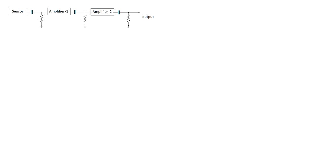
    I am building front end electronics for  capacitance transducer which can work in high temperature environment.

    it has only 2 amplifier stages.

    The first stage is AC coupled to the Second stage and the final output from the second stage is also AC coupled.

    regards


  • Hi Kai,

    I am building front end electronics for  capacitance transducer which can work in high temperature environment.

    it has only 2 amplifier stages.

    The first stage is AC coupled to the Second stage and the final output from the second stage is also AC coupled.

    regards

  • Hi Kiran,

    if the most left resistor is chosen small enough, then the input resistance of OPAmp and its temperature change will not have a great influence on the measurement.

    What resistance are we talking about? And do you need to set a precise time constant with this resistance?

    Kai
  • Hi Kai,

    The value of the resistor will be in the range of 20 to 30 M ohm. This is because the value of Resistor and Capacitor will affect the shape of the waveform.

    Regards
  • Hi Kiran,

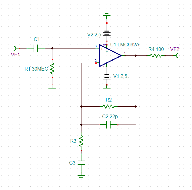
    and, eventually, you can wire the first amplifier as an AC-amplifier with a DC-gain of 1. By this you would not amplify the voltage drop which the input leakage current of OPAmp is causing across the 30MOhm input resistor.

    Kai
  • Hi Kai,

    I am planning to wire the first stage as a unity gain voltage follower (Buffer). Hopefully this will solve the issue

    Thanks for addressing my doubts and  giving  valuable suggestions

    Regards

    Kiran

  • Hi Kiran,

    I would not leave the opportunity unused to already obtain some useful signal amplification in the first stage:

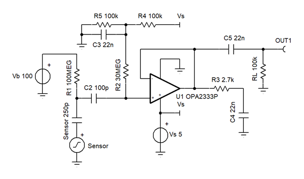
    To take account of the shaping time constant R1 x C1, choose R3 x C3 >> R1 x C1 and R2 x C2 << R1 x C1. Choose C2 >= 22p to provide sufficient phase lead compensation and R4 >= 47R to introduce efficient isolation from capacitive loads. The DC-gain will be 1 and the AC-gain will be (R2+R3) / R3. R2 and R3 should be chosen low ohmically enough to minimize noise and to increase the overall stability..

    Kai

  • Hi Kai,

    Thanks for the advise !!

    I had considered transimpedance amplifier for my design but found that the bandwidth will become limitation.

    I am looking at a bandwidth of about 150K Hz - 200KHz

    regards

    kiran

  • Hi Kai,

    Thanks for the advise !!

    I had considered transimpedance amplifier for my design but found that the bandwidth will become the  limitation.

    I am looking at a bandwidth of about 150K Hz - 200KHz

    Also the input is voltage not either  current or charge

    regards

    kiran

  • Hi Kiran,

    yes, you are right, a TIA seems to be rather unfavorable when using a 30MOhm shaping resistor. I would give the scheme a try which I have recommended you earlier.

    Kai
  • Hi Kai,

    Thanks for the reply!!

    I  require an opamp with high input impedance (>1T ohm). A typical TIA will have relatively low input impedance

    Also the Gain Bandwidth requirements of the opamp will  be high to achieve a bandwidth of 150K Hz to 200KHz

    regards

  • Kiran,

    Can you provide an electrical model of your input source? What is the lower end of bandwidth required?
  • Hi Ronald Michallick,

    Thanks for the reply !!

    At present I am using a third party sensor and I do not have any electrical model for it

    The lower bandwidth limit is not critical in my application. It can be up any value upto 150 Hz

    Can I use OPA2333HT in a voltage follower /Buffer  configuration so that I get high input impedance? 

    the amplitude of my signal is not exceeding 2 V p-p 

    Regards

    Kiran 

  • Kiran,

    That op amp has just barely enough bandwidth for your small signal. Slew rate (large signal) is another matter.  For a sine wave , slew rate needed SR = pi*Vpp*F  = 3.14  * 2Vpp * 200kHz = 1.26V/us which is way more than OPA2333 provides. Also max slew rate occurs only when input differential voltage is large which isn't compatible with a virtual ground concept (assuming both inputs are the same)  

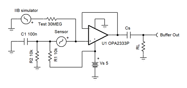
    Regardless of the op amp chosen, you should test the sensor with input bias current to see how it affect the sensor's operation.

    You can do this with a circuit like this or any other circuit that adds current to the sensor. If the sensor can't absorb nano amps of current then you'll have to add resistor to absorb the IIB current. IIB simulated is ("sim voltage" - "U1 out") / 30M. If the sensor easily accepts this small current then the "U1 output voltage wont change much with the emulated bias current. It is also important that the sensor AC output doesn't change with the forced bias current. Keep in mind that just adding the test bias current could affect AC output because the 30M test resistor is also a load to the sensor. 

  • Hi Ronald Michallick,

    Thanks for your advice and interest  in addressing the issue.

    1) The sensor output is a 8K Hz pulse. I have considers the harmonics of the 8KHz  pulse to arrive at the bandwidth requirement of 200KHz.

    should I not consider f = 8K Hz for calculating the slew rate?

    SR = 2πfV

    SR = 2*3.14*8000* 2

    SR = 0.10 volts/ uS

    2)

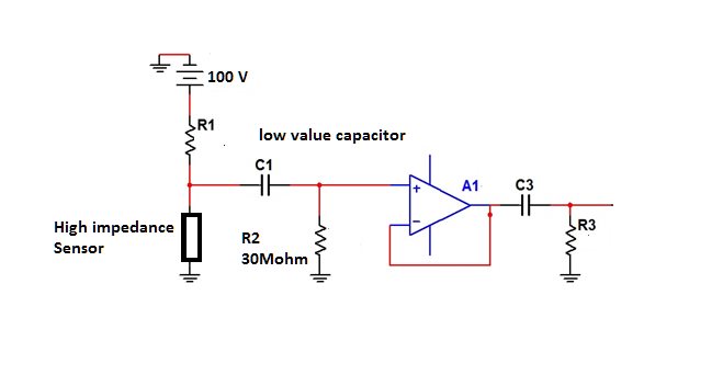
    The sensor I am using has a self capacitance of approximately 100 to 200 pF and is exited by a high voltage DC source of 100V.

    Is this circuit arrangement  (30 M ohm resistor) good enough to  absorb the  Bias Current ?

    I will also try the circuit you have suggested.  Kindly explain what are resistors and capacitors on the input side meant for in your suggested ckt. (like R1 =10K for providing DC bias to the sensor)

    regards

  • HI Ron Michallick,

    I think my slew rate calculation is wrong. Kindly clarify

    regards

    Kiran

  • Kiran,

    To review the slew rate formula, consider the zero crossing which is the fastest slope.
    Say input is Vp *sin (2*pi*f*t), the max slope, dv/dt, is Vp*2*pi*f*1
    So my corrected SR formula is Vp*2*pi*F or Vpp*pi*f
    For a complex waveform just find the fastest edge and measure it's slew rate, dV/dT

    Is the 100V source and R1 symbolic or really added to the circuit. If it is symbolic then the maybe leakage of the sensor is compatible with the input bias leakage current depending on which leakage is greater.

    Zooming out in thought, I have to ask is this sensor is made to work at 210C or hotter? Many sensor manufacturers provide a recommended circuit example showing how to connect the sensor to an amplifier. Is this the case?

    You asked for 1 tera ohm amplifier, however the R2 in your drawing is a heavy load 0.00003 T ohm. If you only need 1T at DC then focus on a low leakage "C1" capacitor.
  • Hi Ronald Michallick,

    1) Is the 100V source and R1 symbolic or really added to the circuit.

    it is really added to the circuit


    2) I have to ask is this sensor is made to work at 210C or hotter?

    Yes, the sensor is built to work at 200 Deg C

    3) Many sensor manufacturers provide a recommended circuit example showing how to connect the sensor to an amplifier. Is this the case?

    No recommendation from the manufacturer

    4) What will be the best opamp  to pick with lower Temperature rating (125 C and above)  ? LMP7721 or anything better

    Regards

    Kiran


  • Kiran,

    With this new information, I can suggest a circuit; I can't suggest a device not rated for the temperature needed.

    R3 and C4 help remove the gain peaking that the simulation shows without these components. If the peaking is not troublesome then leave these components unpopulated to save supply current which also reduces self heating of the op amp. The DC shift from input bias current is IB * 30M, so 5nA would be 150mV shift.


    OPA2333-HT

    OPA2333-HT.TSC

  • Hi Ron Michallick,

    Thanks for suggesting the  scheme.

    1) I use  LT Spice for simulating the ckt. ( It is Free). I could not simulate a variable capacitor, hence tried the circuit practically.  For my application  C2 value cannot be less than 2000pF. I arrived at the best combination of C2 R2 trough experiment. Any other value is affecting the shape of the waveform.

    2) I am expecting a maximum voltage of 2Vpp at the input of the opamp. Since the error introduced is DC in nature (DC offset) and I'm AC coupling it to the next stage it should not be a problem. 

    3) any other parameter to be considered which is critical? please suggest.

    3) Though the signal is single ended can I consider using an Instrumentation amplifier. So that I can use a single chip and also get necessary gain ?

    Regards

    Kiran

  • Kiran,

    1) C2 can be increased at will. It helps set the lower bandwidth and the power up time.
    2) Very good
    3) Just temperature rating and do not use an op amp slower than OPA2333
    4) An IA also works single ended. As always, stay within the recommended input common mode range.
  • Hi Ron Michallick,

    thanks for all the help and suggestions 

    regards

    Kiran

  • Hi Ronald Michallick,

    Is R3 C4 a low pass filter? and how did you arrive at this value

    regards
    kiran
  • Hi Kiran,

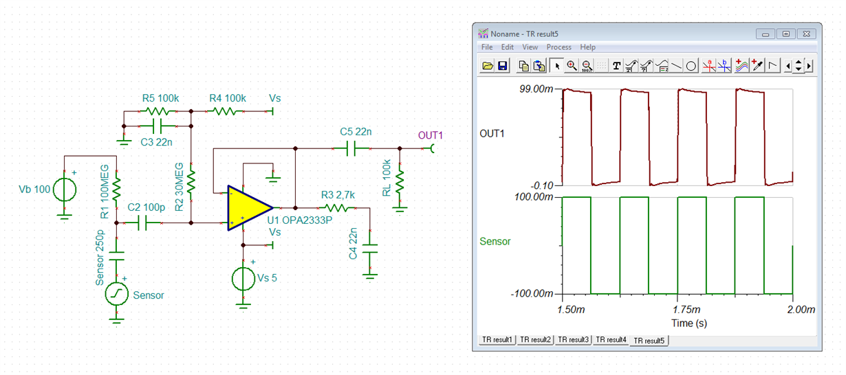
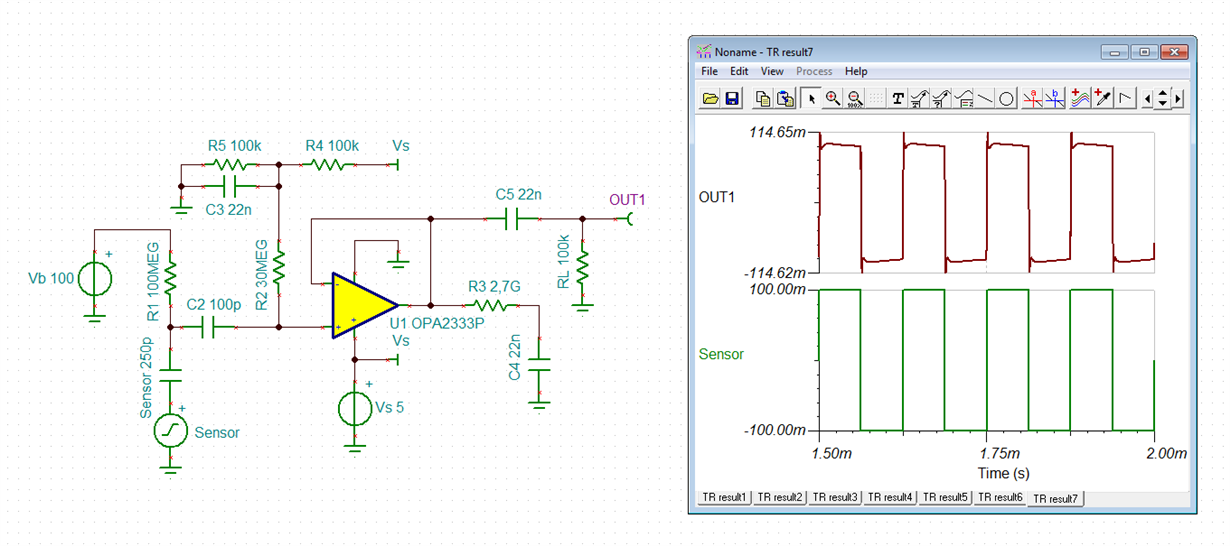
    no, this is a snubber to stabilize the OPA2333. You can see the effect when simulating a square wave with steep edges:

    kiran1.TSC

    Kai

  • Hi Kai,

    Got it ! thanks

    regards
    kiran
  • Kiran,

    With no snubber, I saw 2.1dB gain peaking around 270 kHz, so the 1st snubber was set to 27kHz (one decade down) [2.2nF] and the result was 0.84dB peaking. Another decade down is 2.7kHz with 0.43dB peaking. There was little difference between 2.2nF and 22nF.
  • Hi Kiran,

    the snubber method is a bit tricky. It may or may not work.

    R3 must be as high as the open loop output impedance of OPAmp which is 2k for the OPA2333. So, R3=2k7 is a good choice. After that you try to find a suited C4 to increase the stability. If an OPAmp is instable, a peak in the gain plot in the range of unity gain bandwidth can be seen or a ringing in the step response. See the pictures of my simulation.

    Kai

  • Hi Kiran,

    you can easily check the stability of added snubber with TINA-TI. See the TI's stability training videos:

    training.ti.com/ti-precision-labs-op-amps-stability-3

    Kai
  • Ron Michallick,

    Thanks for the reply

    1) what is the type of capacitor I have to select (22nF)

    2) what is the capacitor suitable for DC blocking? Please advice (like Polyester etc)

    3) How can I accea TINA-TI?

    regards

  • Hi Kai,
    thank you

    is TINA-TI free ? if yes how to download it?

    regards
  • Hello Kiran,

    Yes, TINA-TI is free.
  • Hi Kiran,

    I hope I do not bother Ron when answering this question...

    I would take a good X7R. Of course, you can also use a metalized polyester foil cap.

    Kai
  • Hi Kai,

    what if i'm looking for temperature range over 200 Deg C and discrete component( through hole)

    regards
  • Hi Kiran,

    oops, I overlooked your 200°C requirement. These caps can be used:

    www2.mouser.com/.../N-5g8m

    If they are non-stock, search for another distributor.

    For a 200°C application I would prefer the C0G ceramics.

    Kai

  • Hi Kaii

    thanks

    what type of through hole capacitor is good for DC blocking and filtering application for temperatures < 125 Deg C ?

    regards
  • Hi Kiran,

    I would take C0G (NP0) ceramics:

    www.mouser.de/.../N-bkrdj

    Kai
  • hi kai,

    how about polystyrene capacitor?
    regards
  • Hi Kiran,

    the most polystyrene caps I know cannot withstand +125°C

    Kai