This thread has been locked.

If you have a related question, please click the "Ask a related question" button in the top right corner. The newly created question will be automatically linked to this question.

TINA/Spice/LMC6482: Application circuit of LMC6482

Part Number: LMC6482
Other Parts Discussed in Thread: TINA-TI,

Tool/software: TINA-TI or Spice Models

Hello TI, 
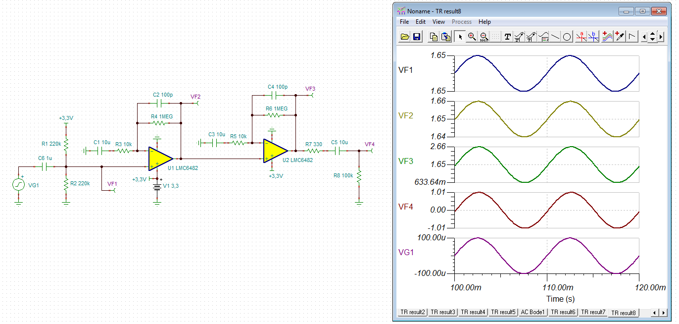
             I am Using LM6482 for Doppler sensor, I am little confuse about there circuit please some one explain the circuit  thanks for your valuable response

why there is using Divider of R1&R2 on input side of the LMC6482 non inverting terminal ...?

Output of IF is 10mV to 100mV floating when the motion is detected 

Output of IF is going through Divider to LMC6482 Non inverting terminal ....?


Thanks and Regards, 
Rahul suarawase

  • Hi Rahul,

    as you power the LMC6482 with a single supply voltage and your input signal is AC, you will need to create a pseudo signal ground at midsupply. C2 in combination with the not shown load resistance removes this bias voltage again.

    Kai
  • Hello Kai,
    C2 in combination with the not shown load resistance removes this bias voltage again. i am not getting you, there is any issues in the circuit, if yes..what is the correct solution ..?

    thanks,
    Rahul
  • Hi Rahul,

    circuit looks good, but has a very high gain:

    rahul2.TSC

    Gain seems too high for your 10mV...100mV input signal. So, I would decrease the gain.

    Kai