This thread has been locked.

If you have a related question, please click the "Ask a related question" button in the top right corner. The newly created question will be automatically linked to this question.

LF398-N: cap charging when hold when power mosfet commutating

Part Number: LF398-N
Other Parts Discussed in Thread: UA741, LM393

Hello,

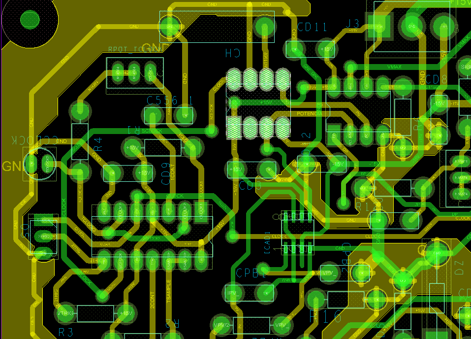
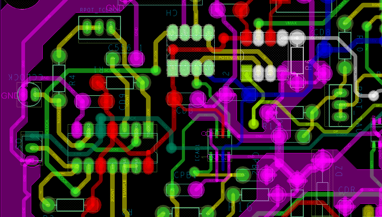
I am working on a project with a boost converter where i need a sample and hold to keep the power value for a short period of time (10 - 50 ms). I have the circuit mounted on a PCB and the S&H works fine until it starts commutate the MOSFET.

here is lf398 datasheet http://www.ti.com/lit/ds/symlink/lf198-n.pdf
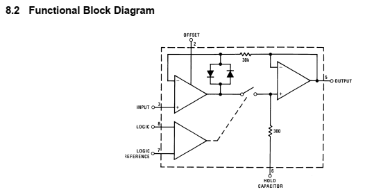
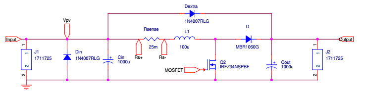
my schematic

In this image u can see that S&H works fine
 

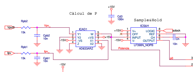
and if i manually modify the power with and external power resistor it also works as u will see in next image


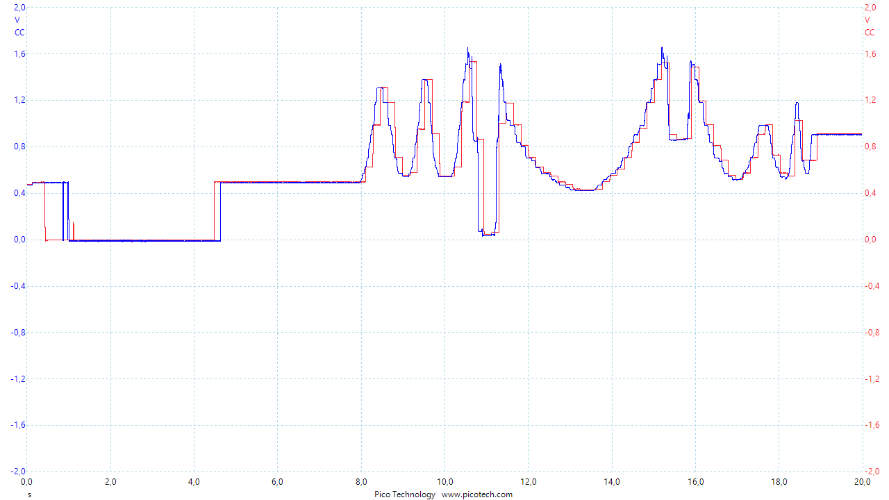
So when my MOSFET starts to commutate while the sample period is on the S&H outputs the same than input (OK) but when is holding time the capacitator starts to charge up to Vcc voltage.

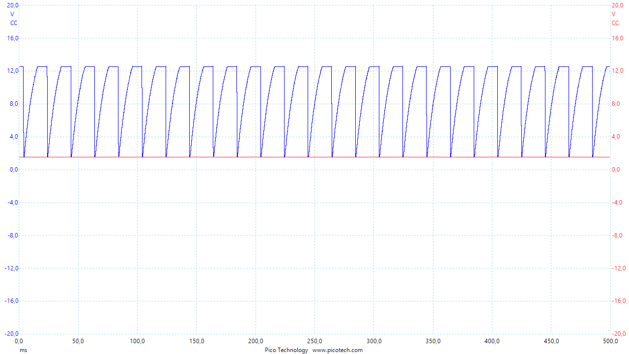
Here Blue is S&H output and red intput in detail to see what really happens. Next one is what happens when it starts to commutate
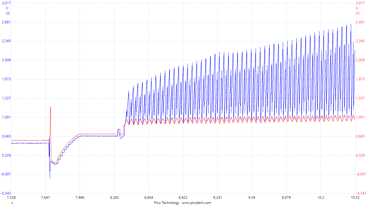

Thins that i tried:

  • mounted the same S&H circuit with all caps that says on datasheet on and external protoboard and it did the same thing.
  • make commutate the mosftet with an external function generator
  • try the same two first point with another LF398 IC

I would be very thankfull if anyone can help me and figure out what is going on with this S&H

  • Fernando

    Your schematic and images did not come through. Please try to upload again.

    You also have a duplicate thread in this forum. I'm going to close that one.

    Regards

    Dennis

  • Hope images are visible now I don't understant why were visible before for me on my browser

  • Hello user6001331,

    I apologize for a late response on this LF398 issue. Actually, I posted a response to the e2e earlier this week but we have been having some problems this week with responses actually being posted to the site. I didn't discover this was happening until a few days later.

    It isn't clear to me from you schematic what the LF389 output drives. You mention "I have the circuit mounted on a PCB and the S&H works fine until it starts commutate the MOSFET." Does the LF389 drive the Q2 MOSFET gate in the diagram, or some other point in the circuit? Where do point 3 and 2 in the upper circuit connect in the lower circuit?

    Thanks, Thomas

    Precision Amplifiers Applications Engineering

  •  LF398 output is compared to its input every 20 ms, in the following images you can see the pcb schematic where lf398 is the selected IC. Bellow, blue is -Vcc , magenta GND and red +Vcc

  • Hello user6001331,

    I haven't been able to respond to your last post until now because I was on international travel where I was unable to access TI's secure VPN.

    Does the LF398 input signal appear to be as expected when the Q2 MOSFET is commutating? Also, you show the LF398 output waveform when the MOSFET is idle and when it is commutating. Your DSO images indicate the output is correct when the MOSFET isn't commutating, and then rises towards Vcc when in hold mode when the MOSFET is commutating. What is the LF398 output driving? It isn't apparent from the schematic.

    Since the LF398 output is behaving as described one thought is the LF398 may be being subjected to EMI being generated when the commutating circuit is operating. EMI can be rectified by the ESD cells or other junctions internal to analog circuit resulting in unexpected behaviors.

    Regards, Thomas

    Precision Amplifiers Applications Engineering

  • I got it fixed, before LF398 input and output where drived into a LM393 comparador. Adding a buffer amplifier ua741 at LF398 output fixed.
    I also incresead sample capacitator from 10 nF to 100 nF.

    Thank you for your support though