This thread has been locked.

If you have a related question, please click the "Ask a related question" button in the top right corner. The newly created question will be automatically linked to this question.

LM2904: High power appears in the production process

Part Number: LM2904

Dear all:

The high power of about 25 power boards appeared on the 500 industrial frequency conversion power supply products produced, which was later analyzed to be caused by the low output gain of LM2904DR operational amplifier.

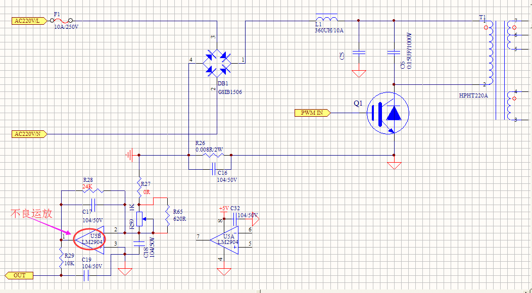
Here is the schematic

Please help to analyze the reason and how to improve it??

Thank  you!

  • Hi Timsen,

    Can you be more specific when you say "High Power"? Does this mean is it outputting more power than expected (as in output current) or does this mean that device is consuming too much power (as in the quiescent current)?

    If you mean that the device is consuming too much power, how much current is the device consuming?

    I recommend checking the phase margin of the amplifier and make sure the output is not oscillating. The capacitor between the inputs of the device (C18) is typically not recommend because it will cause delay in the feedback and degrade the phase margin. I recommend watching our TI Precision Lab videos on Stability for more information.

    Lastly, channel A of the device appears to be floating. This configuration is not recommended. For the recommended configuration I recommend reading Design Guidelines for Devices with LM324/LM358 Cores and The Unused Op Amp - What to do?.

    Thank you,

    Tim Claycomb

  • Dear Tim:

           thanks for your reply.

    1, High power means high power output.The power of our power supply is calculated by the constant power of input voltage and current to control the power supply. Now there is a problem with the amplification of LM2904 current. For the same sampling input current, the output voltage of the defective operational amplifier is lower than the output voltage value of the normal operational amplifier, so the output power of the power supply is on the high side.

    2, The capacitance of C18 has little relation with the high output power. If we replace the operation amplifier of the power board with the high output power, the output power will be normal.

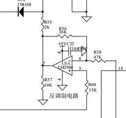
    3, Channel A of LM2904 is not be floating, but the schematic diagram is not visible, as shown in the figure above, there are some schematic diagrams.

    We have produced 500 sets of industrial frequency conversion power supply products in total, and 25 sets of power supply boards have high power problems at present.Please help to analyze the main cause of the defect, thank you!


  • Hi Timsen,

    What is the expected output voltage of the LM2904? What is your measured output voltage?

    Can you please provide oscilloscope shots of the output of the LM2904? This will help to determine what may cause the issue.

    What is the load connected to the OUT node in your schematic?

    Thanks,

    Tim Claycomb

  • Hello Timsen,

    The gain of the current sense amplifier is not the issue. The gain is correct and set to -R28/(R59||R65). Keep in mind that gain is dVOUT/dVIN (for example (VOUT2-VOUT1)/(VIN1 - VIN2). Gain is not VOUT/VIN.

    The issue may be related to input offset error. This natural op amp error voltage will create an offset error in the output voltage that is Vos*(1+R28/(R59||R65)). This error voltage does not change circuit gain as described in the previous paragraph. Every sample of LM2904 has two different Vos values (one for each amplifier)  

    C18 may be a stability issue, if a low pass filter is desired then a different connection is needed.

    What is the purpose on the potentiometer?

  • Hi Timsen,

    Have you been able to identify the root cause of your issue? If not, please reply back with answers to my and Ron's questions.

    Thank you,

    Tim Claycomb