This thread has been locked.

If you have a related question, please click the "Ask a related question" button in the top right corner. The newly created question will be automatically linked to this question.

LMV796: LMV796 nagative input/output

Part Number: LMV796
Other Parts Discussed in Thread: LM2904

Dear Team:

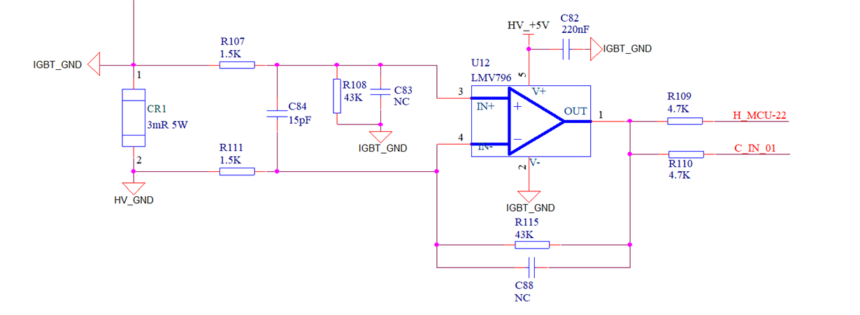
    Please check the schematic as below:

    Customer used the IGBT_GND for LMV796 reference GND, and the input is HV_GND, so does the input is a negative voltage, and the output is also a negative voltage?

    The output(H_MCU-22) is to MCU, but the MCU can not receive a negative voltage. My question is if output is a negative voltage, what method can turn the voltage to positive? Or the LMV796 design is unreasonable now, need to change the design?

    Customer want to monitor the IGBT current.

    Thanks!


    Thanks!


Regards!

Eric Shen   

  • Hello Eric,

    The input voltages to the difference amplifier stage are ideally 0V and negative IGBT current * 0.003ohms and the output voltage will be positive IGBT current * 86m ohms. This is true until the output get to 5V (about 58 ampetpes). After that, the inverting input may become negative.

    The output is a positive voltage in proportion the the IGBT current.

  • Hi Ronald:

        Thanks!

        Now there's another problem:

        Customer test the circuit now, but there are some changes in the circuit design, the LMV796 GND is HV_GND, the 5V reference GND is also HV_GND now.

        The input conditions and output results are as follows:

        IGBT current= 10.15A, R111=1.5K, R115=47K(not 43K) Gain=32.33 Vout=1.0875V, the theoretical calculation Vout is 0.984V, there is lager error, close to 10%

        Another data: IGBT current= 2.5A, R111=1.5K, R115=47K(not 43K) Gain=32.33 Vout=0.263V, the theoretical calculation Vout is 0.243V, there is lager error, close to 10%.

        I don't know why? Please help to analyze it, thanks!

    Regards!

    Eric Shen


  • Eric,

    The 47k resistor only at R115 will degrade the common mode rejection unless R108 is also changed to 47k.  The gain is 31.227 if just R115 is 47K.  = 1+(47/1.5)*43/(43+1.5).  If both were 47K the gain would be 31.333 = 47/1.5.  I plotted your data with an assumed 0A = 0V and it's a straight line.  The gain of the line matches a sense resistor of 3.4m Ohms. This is a 13% error. That error is cause by resistance error in the sense resistors and amplifier resistors or the kelvin connection of the sense resistor is improperly routed. The op amp can't create a gain error, but it can make small offset error.     

  • Hi Ron:
         I check with my customer, the data I gave you before is tested when R108 is 47K, and all the resistors on this circuit are 1% accurate.

         If the gain = 31.333, the theoretical value is smaller(0.954V) and the deviation from the actual measured value(1.0875V) is even bigger.  My customer also remove the R108 to test, the test result were similar.

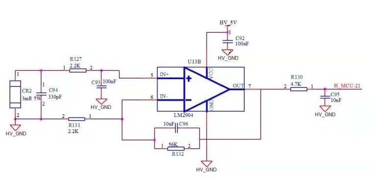
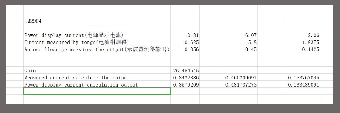
         And my customer do a another test, they used LM2904 design as below, the test data error is small, about 1%:

         So I still don't understand why LMV796 has a big error(10%), and LM2904 has a small error(1%) under the same conditions.

     Regards!

     Eric Shen

  • Eric,

    The circuit shown changes every time. In the last schematic, the LM2904 was used which is a slow op amp and the capacitors are bigger. Perhaps the lack of capacitors in the first schematic is letting too much AC noise getting through. 

    Can you install a LMV796 in a board that uses the last schematic so see if it works the same as LM2904 or not. 'Apple to Apples' comparison.