A related question is a question created from another question. When the related question is created, it will be automatically linked to the original question.
If you have a related question, please click the "Ask a related question" button in the top right corner. The newly created question will be automatically linked to this question.
Peculiar would me the name that comes to mind - 3 pieces
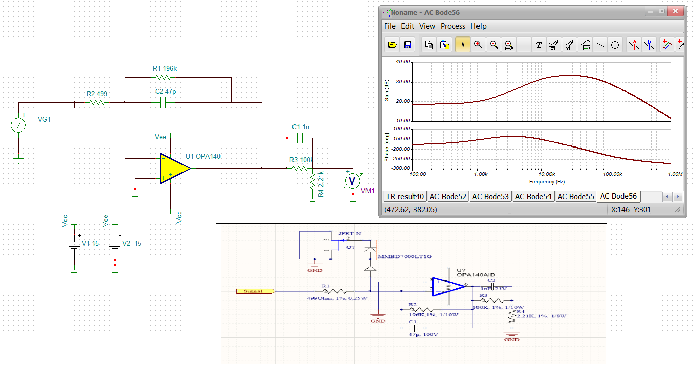
1. The inverting DC signal gain is very high, -196k/499 =-392V/V. The 11MHz GBP then gives a 132kHz signal bandwidth while the feedback C also puts in a 17kHz pole that will dominate
2. The didoes and JFET are overdrive shunt. As the amplifier overdrives, the input V- voltage increases from ground until it turns on that path. The diode polarity tell me they only expect positive signals.
3. The output is big DC attenuator, 2.2k/(102k) = .01256.so the net DC gain is .01256*392 = 8.45V/V. The shunt 1nf starts to take the output attenuator towards zero starting at 1.59kHz.
I am sure the response shape looks like a bandpass of some sort. If you want a really sharp BandPass should look at the DAMP BP discussed in these e2e occasionally.
Peculiar would me the name that comes to mind - 3 pieces
1. The inverting DC signal gain is very high, -196k/499 =-392V/V. The 11MHz GBP then gives a 132kHz signal bandwidth while the feedback C also puts in a 17kHz pole that will dominate
2. The didoes and JFET are overdrive shunt. As the amplifier overdrives, the input V- voltage increases from ground until it turns on that path. The diode polarity tell me they only expect positive signals.
3. The output is big DC attenuator, 2.2k/(102k) = .01256.so the net DC gain is .01256*392 = 8.45V/V. The shunt 1nf starts to take the output attenuator towards zero starting at 1.59kHz.
I am sure the response shape looks like a bandpass of some sort. If you want a really sharp BandPass should look at the DAMP BP discussed in these e2e occasionally.
Dear Michael Steffes,
Your answer is very detailed. But I still don't understand item number 2. How can such polarized diodes suppress the negative signal?
1. Normally the voltage across the diode is zero if the op amp is in range
2. Once the op amp hits its output rail,which will happen for a pretty low input signal given all the gain, the V- voltage on the op amp rises quickly (open loop) turning that first diode on.
3. I don't see supply voltages on the OPA140,or I could tell that input voltage
4.Actually, that first diode is all you need, it is going to ground and nothing changes with the other elements in that path.
1. Thông thường điện áp trên diode bằng 0 nếu op amp nằm trong phạm vi
2. Khi op amp chạm vào đường ray đầu ra của nó, điều này sẽ xảy ra đối với tín hiệu đầu vào khá thấp với tất cả mức tăng, điện áp V trên op amp tăng lên nhanh chóng (vòng hở) bật diode đầu tiên đó.
3. Tôi không thấy điện áp cung cấp trên OPA140 , hoặc tôi có thể nói rằng điện áp đầu vào
4. Thực tế, diode đầu tiên đó là tất cả những gì bạn cần, nó sẽ được nối đất và không có gì thay đổi với các yếu tố khác trong đường dẫn đó.