This thread has been locked.

If you have a related question, please click the "Ask a related question" button in the top right corner. The newly created question will be automatically linked to this question.

MULTI-CAL-SYSTEM: No output to DMM

Part Number: MULTI-CAL-SYSTEM
Other Parts Discussed in Thread: PGA308, , PGA308EVM

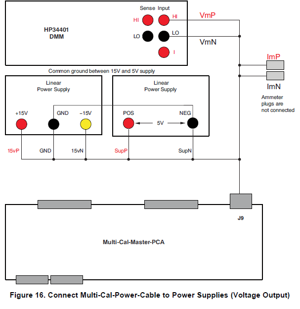
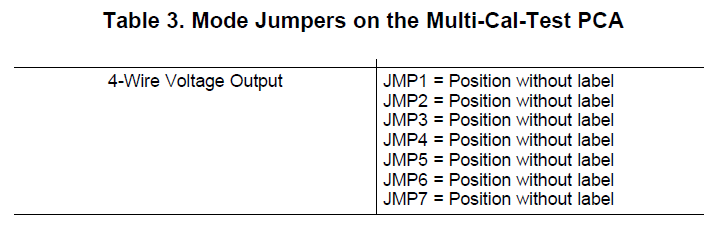
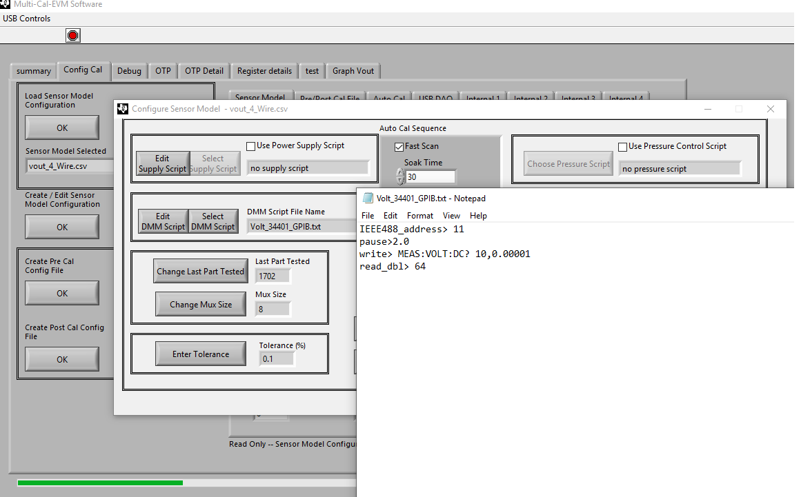
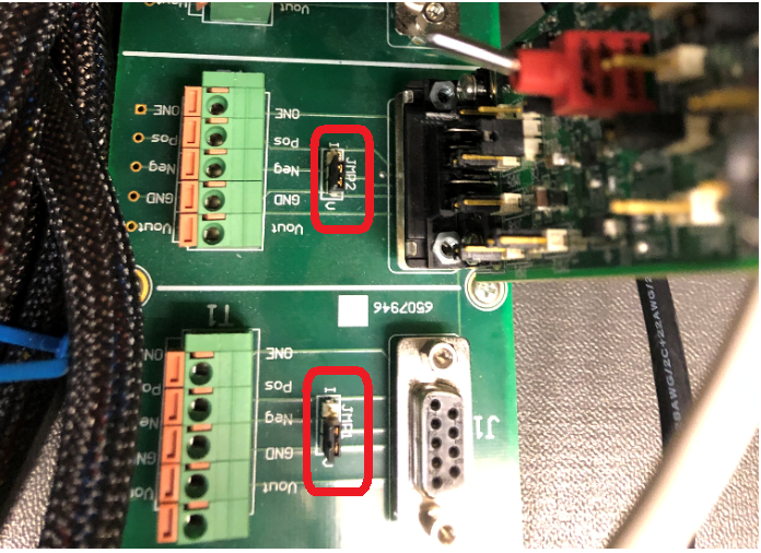
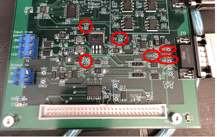
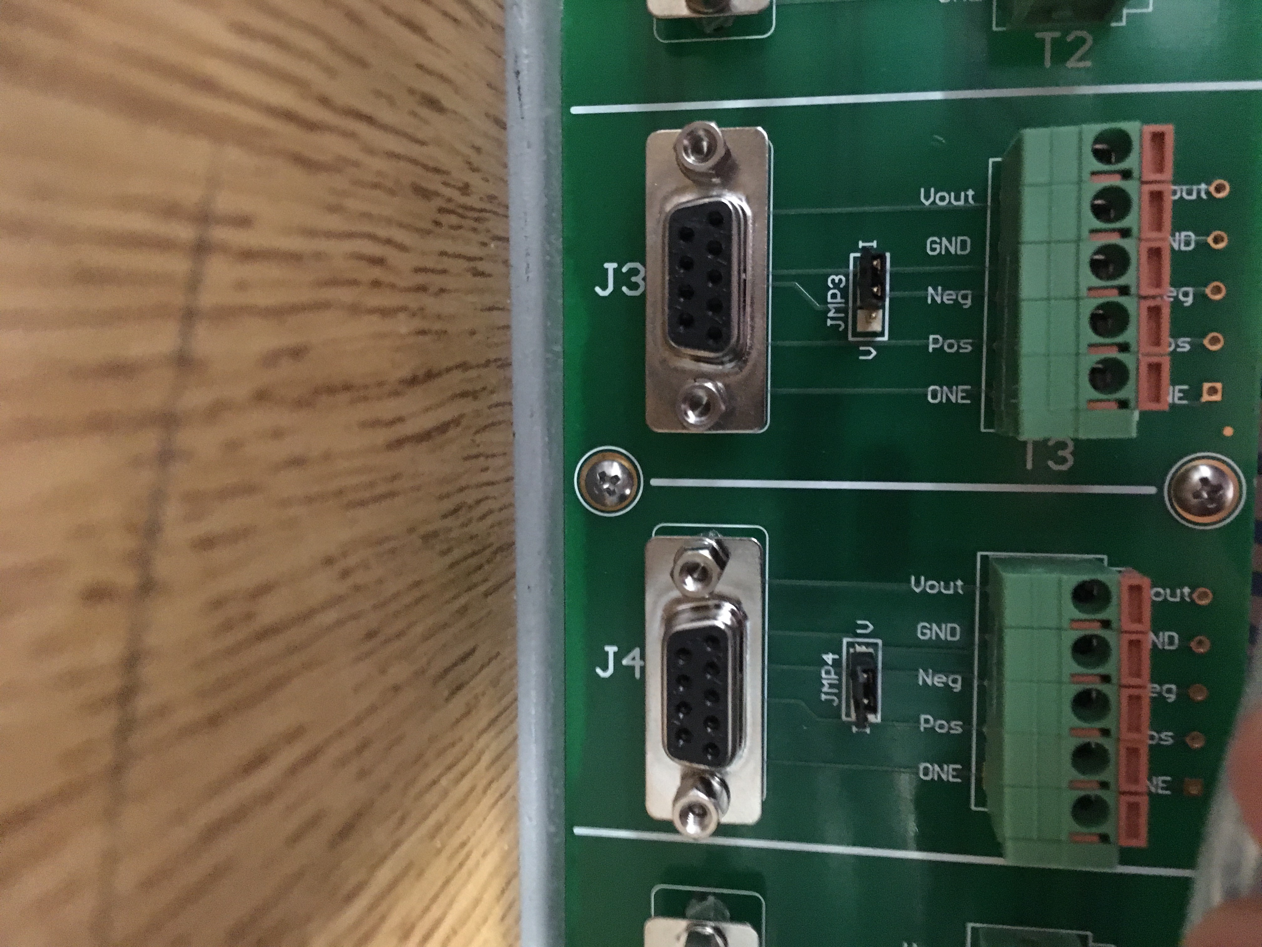
I am running the multi cal system with two test PCA cards. The jumpers on the card are set up for a 4-wire. I am running a version of the 'vout-4-Wire.csv' model configuration that is a default. The only modification I made was changing the DMM script from RS232 to GPIB. I am using a keysight 34401A so I am using the default DMM script with only GPIB address changed. It is connected through a National Instruments GPIB-USB-HS cable. I have verified the communication with the DMM in NI MAX with an IDN?\n command.

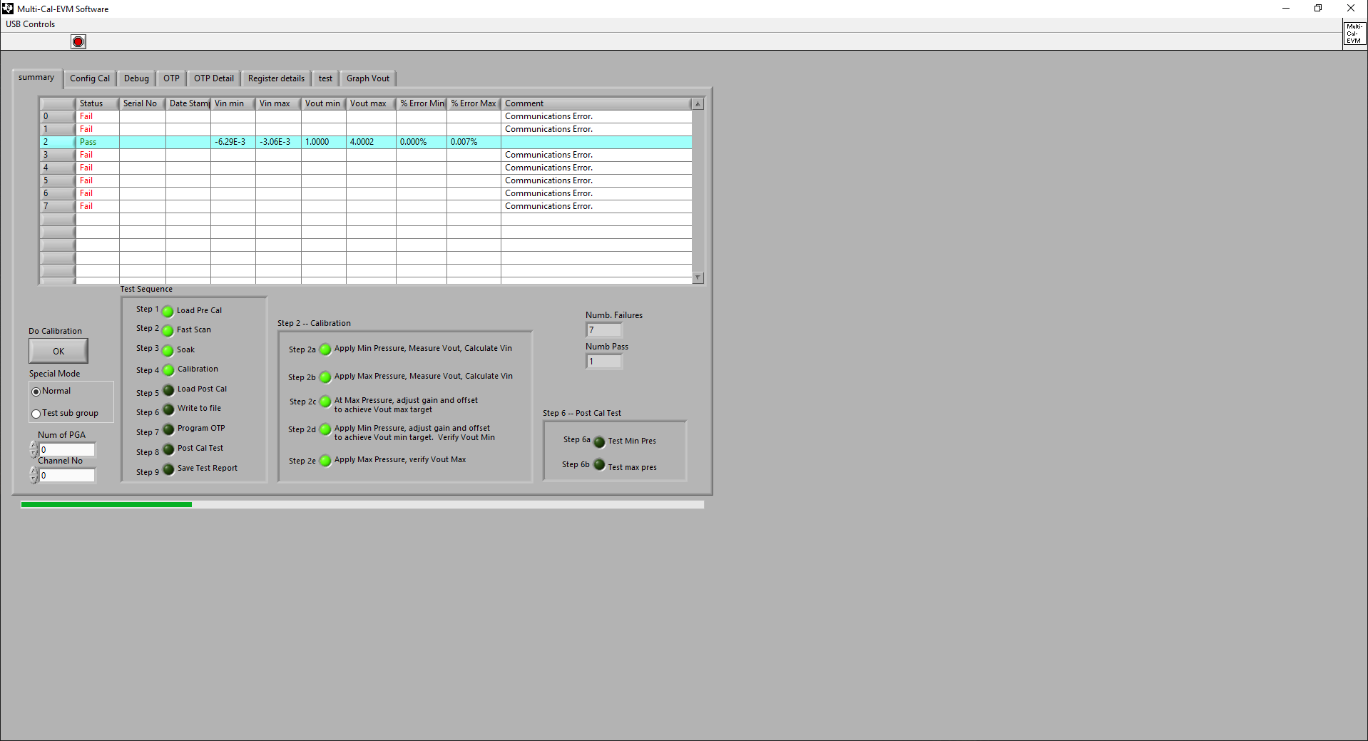
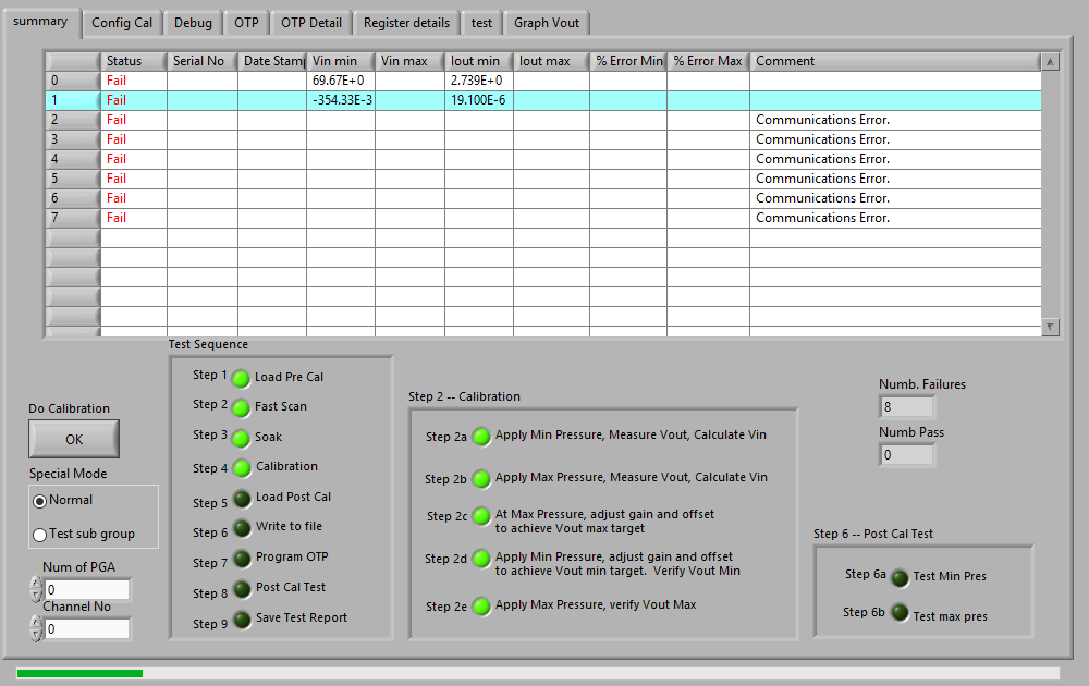
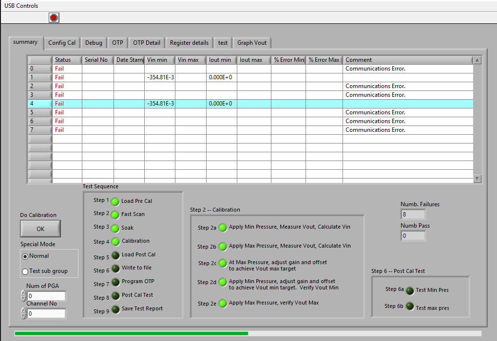
When I run the calibration, fast scan identifies the two channels with PCA test cards connected (I have run with the cards in different positions to eliminate specific plugs being the problem). The attached picture shows the result of calibration. In this picture, the card are connected to plugs 1 and 4, and both had passed the fast scan check, and failed after the first attempt to measure the minimum stimulus. During the calibration, the DMM front panel reads zero through the entire calibration.

Any ideas as to why this may be happening or anything I can try to test?

Thanks for any help,

Matt

  • Hello Matt,

    I am assuming that you are using the MULTI-CAL_SYSTEM with the PGA308.  Is this correct?  There are a number of reasons why the meter may not provide a reading.

    Please verify the following:

    - Do you get any errors pop-up while communicating with the meter? If this is a communication error, typically an error will display in the GUI. 

    - Are you using the standard Multi-Cal-Test PCA Card or a Custom PGA308 board?  If you are using a Custom board please provide the schematic of the Custom card.

    - Are the voltage meter (and power supply) connections made through connector J9 on the Multi-Cal-Master PCA?  Are the meter connections set up for voltage measurement (VmP/VmN)?  (Ammeter plugs not connected)  Can you verify continuity on the Multi-Cal-Power Cable between the multimeter terminals and the DSUB9 female connector using an external meter?   If using the 34401A front panel terminals to connect the multimeter, are the 'front' terminals selected on the 34401 panel button? 

    - Are the 4-Wire Voltage output connections setup as shown on Table 3? Please see below:


    - Can you please verify with an external meter that the Multi-Cal-Test Card is being powered up properly when testing?  What are the voltage supply levels on the test card

    I will go ahead and setup the Multi-Cal system using the external meter with NIs GPIB-USB-HS and verify the system works on my side (I believe I have used this multimeter connection before with the PGA308 Multi-Cal).

    Thank you and Regards,

    Luis

  • Hi Luis,

    -I do not receive any errors while communicating with the meter. It doesn’t seem to respond at all when the calibration is running.

    -I am using the standard Multi-Cal-Test PCA card that came with the starter kit.

    -I am making connections through connector J9 with the Vm+ and Vm- plugs. The ammeter plugs are not connected to anything. I checked the continuity and verified that pin 5 on the SUB is tied to Vm- and Pin 6 on the DSUB is tied to Vm+. I am currently connected to the rear panel, and I have the rear selected with the switch. I have also tired connecting it to the front panel instead, and it made no difference. The multimeter terminals are connected as shown in figure 16 in your post.

    -Jumpers on the PCA cards are positioned as specified for a 4-wire in the attached chart.

    -I am not sure that I tested this correctly, but I connected the PCA boards then I measured between ground and ONE pins on plugs with a PCA test card, and the voltage is 1.5V. When I measure this on the plugs on the board that don’t have a PCA test card, the voltage measures 4.5V (see picture). I also measured between ground and all the other pins and they measure 0V. If I am measuring this incorrectly let me know

    Thanks,

    Matt

  • Hi Matt,

    I have tested the MULTI-CAL-SYSTEM with the PGA308 Test card and connecting the 34401A meter using NIs GPIB-USB-HS adaptor.  I am not able to immediately reproduce a multimeter issue unless the meter has been programmed with the wrong address; or the GPIB-USB-HS is not properly connected to the PC or DMM.  If there is a mismatch on the address and DMM script, or a connection issue with the GPIB adaptor, an error displays in the GUI showing that there is a communication error.

    The voltage meter probes connect through connector J9 on the Multi-Cal-Master board, using pin J9.6 (DVM-) and pin J9.7(DVM+) of the DSUB9 connector. 

    When performing the calibration routine, when a specific test card is selected (using the vout-4-Wire mode), you should see a voltage supply level between the 'Pos' and 'GND' test points on the multi-Cal-interface card equal to the voltage level of the external linear supply (SUPP/SUPN) you are applying.  The standard PGA308 test card has an internal local voltage regulator limiting the voltage to +5V; therefore, you should use an external voltage of (SUPP/SUPN) larger than >+5.55V and less than 40V.  Also, while running the calibration routine, you should be able to probe with an external meter and measure the output of the PGA308 device (Vout test point in the interface multi-cal-interface card).  This voltage should be in agreement with the 34401 meter measurement.

    As you have mentioned, you may select the "Volt_34401_GPIB.txt" voltage meter script when using the test card on the 4-wire mode.  To change the DMM script, you select the "Config Cal" tab, click on the "Create / Edit Sensor Model Configuration" button.  The 'Configure Sensor Model" window appears, where you may Edit or Select the DMM Script as shown below.

    Below is the display capture of a calibration in progress on channel 2 when using the 34401 through the GPIB:

    Attached is the DMM script file I am currently using, were you can change the GPIB address on the file per your requirement. 

    Volt_34401_GPIB.txt
    IEEE488_address> 11
    pause>2.0
    write> MEAS:VOLT:DC? 10,0.00001
    read_dbl> 64

    Please let me know if you are unable to measure the voltage supplies properly on your PGA308 test card.  In addition to checking the DSUB9 supply cable, please consider checking continuity on the DSUB37 connector cables connecting the multi-cal-master PCA to the multi-cal-interface PCA boards.

    Thank you and Best Regards,

    Luis

  • Hi Luis,

    I do not get any communication error in the GUI. I have verified the communication between the computer and DMM. I have the script setup to match the address of the DMM, in my case they are both set to address 0.

    I double checked the continuity on the multi-cal-power cable and verified that it matched this table shown in the multi-cal-cable user’s guide.

    So I performed a calibration and measured between the ‘POS’ and ‘GND’ pins, and it measured 4.989V (the power supply I’m using is fixed at 5V so this makes sense). Then I ran a calibration again and measured between ‘vout’ and ‘GND’ with a hand meter and measured 3.2V at the time of calibration. At the same time the DMM was reading 0.0V. So there must be a break somewhere to prevent the signal from getting to the DMM. I have the 81 mV jumper selected for the low on the test card so 3.2V is way higher than I should be getting.

    Since you mentioned there needs to be at least a 5.55V supply to the test card, I swapped out the power supply for the DUT and used a different one set to 7V and ran a calibration again. This yielded the same result where I measured 3.2V on the output with a handheld meter, and I verified there was in fact 7V to the test card across ‘POS’ and ‘GND’ during calibration. The DMM still didn’t not read anything.

    I verified the continuity of the multi-cal-interface cable per the chart below, except the shield is only tied to pin 1, pins 10, 20, and 29 are all open.

    Let me know your thoughts

    Thanks,

    Matt

  • Hi Matt,

    Thank you for the information.  Please verify the following:

    1) On Multi-Cal-Interface Card, verify JMP0 through JMP8 are on the voltage (V) position as shown below to support voltage mode. 


    2)  On the Multi-Cal-Master, assuming that the +15Vp and -15Vn external supplies are connected through DSUB9, can you please check with handheld meter the test points below:  -15V, +15V, -10V and +10V as shown on the image below. On the Multi-Cal-Master, Check the voltage on D- and D+ voltage with handheld meter during calibration; the min/max output voltage should show for a couple of seconds during the cal process.  Test points shown on image below.  Let me know if this do not show the correct voltages.


    3)  If issues persist after checking the above, if possible, can you please connect the 34401A meter HI/LO inputs directly to 'Vout' and 'NEG' test points on the Multi-Cal-Interface card on the selected channel and see if cal is successful in one channel?  This is only to verify/check the meter and the GUI software is working properly, overriding all the mux hardware/ connections of the Multi-Cal-system.

    If issues persist, let me know and I will contact you via email.

    Thank you and Regards,

    Luis

  • Hi Luis,

    1)      All jumpers are in the voltage position. But as a note the board is labeled incorrectly on channel 3 only, where the “I” and “V” are swapped. I checked the continuity and verified that the “I” position on channel 3 ties “GND” and “Neg” just as it does on the “V” pin on all other channels. So on channel 3 only, I have the jumper moved toward the “I” pin. Picture of the label below.

    1)      I probed between +15 and -15 and measured 29.64V and probed between -10 and +10 points and measured 20.09V. Then I probed between D+ and D- while I ran a calibration and measured 0V through the whole process.

    2)      I connected the DMM directly to ‘VOUT and ‘NEG’ on the interface for channel 1 and got the result shown below. At the time of the test, the low jumper on card 1 was selected to 30mV, and the high jumper was on 98 mV.

    Obviously channel 1 is now reading something, but it is not correct. What is it that makes this fail at this point? Where is the criteria that says that these values fail?


    Let me know

    -Matt

  • HI Matt, 

    I will be contacting you today via email regarding the issue with the Multi-Cal-Master board. 

    The PGA308 Multi-Cal system demonstration board is based on the PGA308EVM evaluation module. 

    There is a series of videos that discuss the PGA308EVM operation and the auto calibration process in detail.   In particular, part 2 (section 8) goes through an example of a calibration and configuration example that may be useful.  Essentially, during the calibration process, a minimum  and maximum signal is applied at the inputs of the PGA308 to represent the offset and full-scale signal of the sensor.  On the PGA308 test card, the board incorporates a sensor emulator circuit using voltage dividers.  The user can set up the "Sensor Low" and "Sensor High" voltages by configuring the shunt jumpers on the voltage divider circuits.  During the calibration process the user can switch between "Sensor low" and "Sensor High" using switch SW1.  After the calibration process is complete, the expected PGA zero and PGA full-scale outputs are compared against the programmed targets and tested against the tolerance setting in the GUI (default is 0.1%, but the user can change this setting).

    Below is a link of a series of videos discussing the PGA308EVM user guide that you will find helpful.

    PGA308EVM Video Quick-Start User Guide (part 1)

    PGA308EVM Video Quick-Start User Guide (part 2) 

    PGA308EVM Video Quick-Start User Guide (part 3) 

    PGA308EVM Video Quick-Start User Guide (part 4)

    Below is the PGA308 device User Guide that discusses the device in great detail.

    PGA308 User's Guide

    Thank you and Regards,

    Luis