This thread has been locked.

If you have a related question, please click the "Ask a related question" button in the top right corner. The newly created question will be automatically linked to this question.

PGA308: PGA308 Vsj Pin Capacitor

Part Number: PGA308
Other Parts Discussed in Thread: PGA309

Hello,

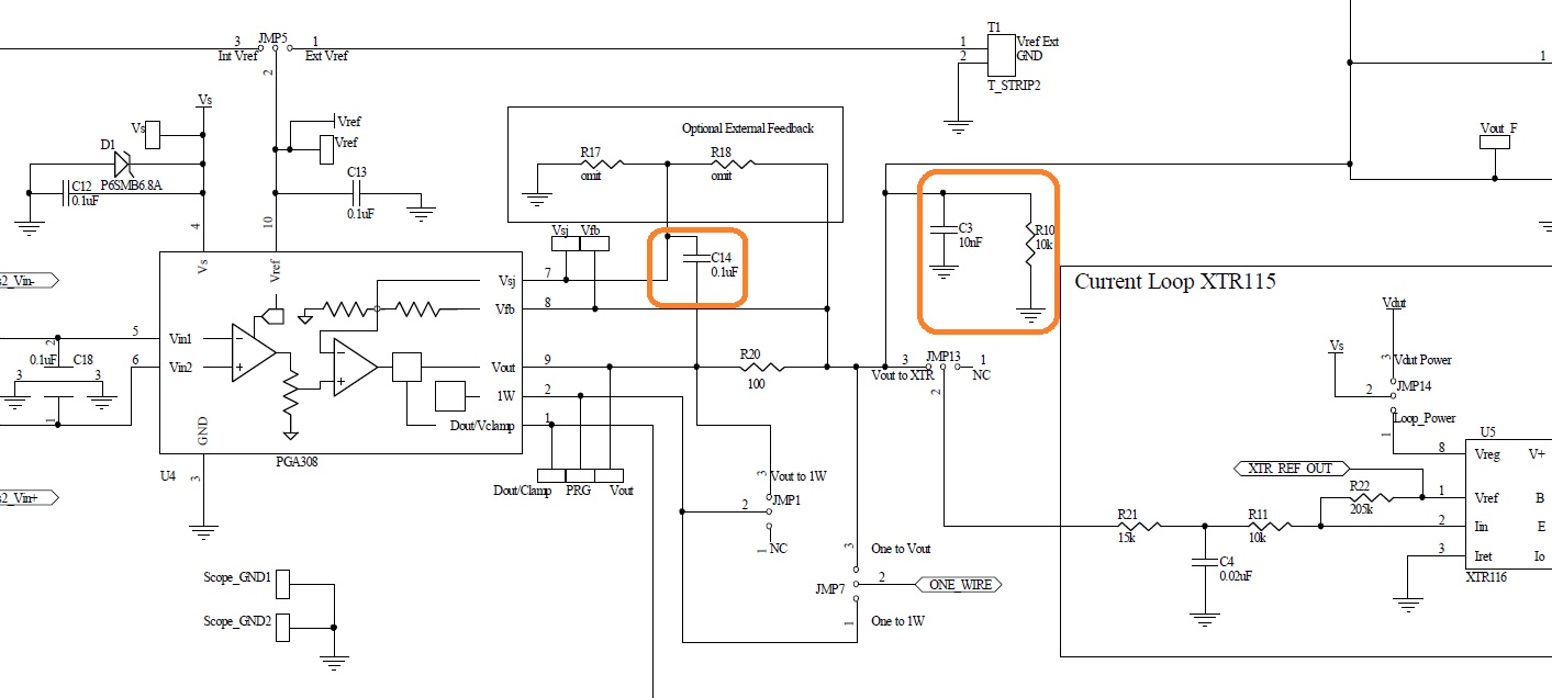
1- PGA308 How to calculate the capacitor (C14) value between Vsj pin and Vout. I didn't see any examples in the technical documentation.

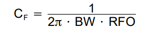
2- What is the reason for using R10 resistor and C3 capacitor?

Thank you

Mert


  • Hi Mert,

    There is an application note on the PGA309 that discusses noise filters specific  for the PGA309 and discusses the capacitor used between the PGA309 VSJ pin and the output of the PGA to select the filter:

    Application Report SBOA110A: "PGA309 Noise Filtering"

    Essentially, the capacitor CF (or C14 in the schematic above), is selected depending on the desired filter corner frequency (or the desired amplifier bandwidth).  The filter corner frequency is a function of the time constant that forms between the internal PGA30x feedback gain resistor (RFO) as explained on the application note. 

    The CF capacitor value is calculated using the equation below, where BW is the desired amplifier bandwidth and RFO is the internal PGA30x feedback resistor.

    The amplifier design architecture of the PGA308 is similar to the PGA309 device, although there are differences between the devices.

    It is important to highlight, the PGA308 offer output amplifier gains of 2, 2.4, 3, 3.6, 4, 4.5, 6 and the internal  RFO resistor values on the PGA308 are different than the values of the internal resistor values of the PGA309. The RFO internal resistor values for the PGA308 are indicated on the table below: 90k, 105k, 120k, 130k, 135k, 140k, 150k   for gains 2, 2.4, 3, 3.6, 4, 4.5, 6 respectively:

    The 10 nF and load components at the PGA30x output are in place for an optional RFI/EMI filter connected between the output and the ground of the module.

    Thank you and best Regards,

    Luis

  • Hi Luis,

    Thank you for your answer. Is there a recommended bandwidth?

    Mert

  • HI Mert,

    The bandwidth requirement depends on your application, in other words, it depends on the bandwidth of the signal you are measuring, and/or how fast you need the amplifier to settle after a change on your bridge sensor.  If this system does not have strict bandwidth requirements, in general, setting the filter to a lower frequency will produce lower noise results. 

    In the case of the PGA309 example on the Application Report SBOA110A: "PGA309 Noise Filtering", using a filter of 100-Hz BW produces the lowest output peak-to-peak noise as shown below.  Although the PGA308 noise results may not be exactly the same, the same trend applies where reducing the bandwidth will reduce the noise.

    Thank you and Regards,

    Luis