This thread has been locked.

If you have a related question, please click the "Ask a related question" button in the top right corner. The newly created question will be automatically linked to this question.

OPA4197: Current Consumption

Part Number: OPA4197
Other Parts Discussed in Thread: TINA-TI, OPA197, OPA2191

Hi,

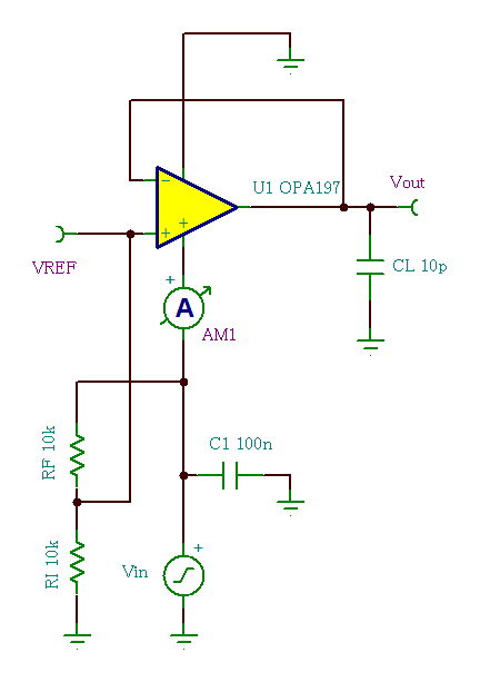
The symptom exceeding the current consumption which is mentioned in OPA4197 data sheet were confirmed from 2V to 3V during power-on. Additionally, the same symptom cannot be obtained even if a simulation is performed with TINA-TI.
Although the power supply voltage from 2V to 3V is outside the recommended operating voltage range, the power supply may not power up if the LDO drive capability is low.
Could you please confirm whether the same symptom can be replicated and tell me the root cause ?

OPA197_Iq.TSC

I will continue to discuss via a private message if you can accept my friendship request.

Best regards,
Kato

  • Hello Kato-san,

    It isn't clear what the exact behavior is you are describing so I may need some clarification if I have misunderstood your questions.

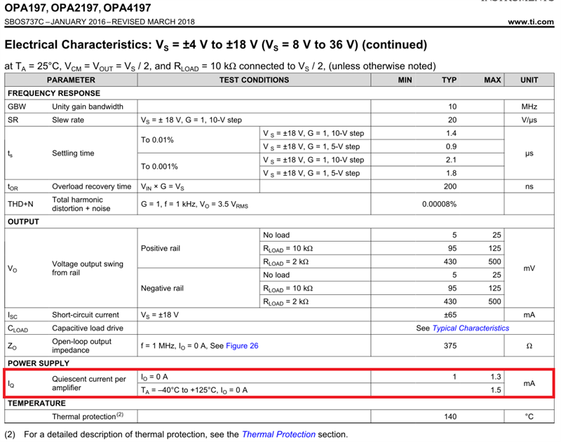
    Is it the OPA4197 is drawing operating current that exceeds the 8 V to 36 V, 1.3 mA, or 1.5 mA maximums during power up while V+ is between 2 V and 3 V? In that supply range the table limits are not applicable because it is outside the stated supply range and the internal circuits are not operating in their linear operating regions. During power up the power on reset (POR) circuits are forcing the output low until the minimum supply operating voltage is attained at which point they turn off and linear operation is attained.

    The OPA4197 simulation models do not mimic the operating current behavior you are observing. The models are built and optimized to replicate operation in the specified supply operating range.

    Regards, Thomas

    Precision Amplifiers Applications Engineering

  • Hi Thomas-san,

    Thank you for your quick response.

    Actually, OPA4197 is used within the recommended operating voltage range. However, the current consumption Iq/ch exceeds 1.5mA when the power supply voltage transitions between 2V and 3V during power-up.
    I would like to confirm just in case, so is this symptom that the output is forcibly pulled to GND when OPA4197 performs the power on reset(POR) ?
    Additionally, is there mentioned in OPA4197 data sheet regarding the POR that causes this symptom ?

    Best regards,
    Kato

  • Katoh-san,

    I spoke with the OPA4197 design team and received a better explanation regarding the POR operation. In the case of the OPA4197 the POR renders the output a high impedance during power-up, rather than forcing the output into a low state as I early discussed (the OPA2191 does that). The purpose of the POR in this op amp is to limit the output stage shoot-through current during power-up. Likely, the current increase you are observing is the result of a small, momentary shoot-through current flowing from V+ to V- when the supply slews from 2 V to 3 V. Design tells me the shoot-through current would be substantially higher if the POR were not in place.

    Design details of this level are not discuss in the OPA4197 datasheet.

    Regards, Thomas

    Precision Amplifiers Applications Engineering

  • Hi Thomas-san,

    Thank you for the information.

    The current of 1.5mA or more flows when the power supply voltage is actually fixed between 2V and 3V. So, could you please tell me the current value which flows as a design value ?

    Best regards,
    Kato

  • Kato-san,

    There is a lot going on with the current flow internal to the OPA4197 during power up. Since the internal junction capacitances such and compensation capacitor are being charged the current that is drawn by the op amp is a function of the rate at which the applied supply voltage ramps. A faster supply ramp will draw a higher current for a shorter time than a slower ramp. Therefore, it is not possible for us to say just what the current will be between 2 and 3 V. About the best estimate we can make is it could be several times the stable quiescent value.

    Regards, Thomas

    Precision Amplifiers Applications Engineering

  • Hi Thomas-san,

    Thank you for the comments.

    Could you please tell me the necessary current under specific conditions(e.g.: slew rate = XX V/us) during power-up since the power supply cannot be started if the LDO drive capability is low ?
    It can be explained to our customer if there is an actual measurement value.

    Best regards,
    Kato

  • Hello Kato-san,

    The actual op amp operating current during each of the tests is monitored to make sure that a high trip current isn't exceeded. The trip current level is set to protect the ATE should a defective op amp - one that would drawn excessive current - from damaging the equipment. No precise measurement of the supply current is made during a particular test such as a slew rate test.

    A point that came up in my discussion with Test Engineering regarding the OPA4197 operating current during test is the effect the power supply decoupling capacitors have on the supply current during power up. Previously, I had mentioned the role that power-up time played in the power supply current as the OPA4197 internal junction and compensation capacitances charge (i = C dv/dt). However, if power supply decoupling capacitors are in place - as they should at the op amp power supply pins - their capacitance such as 100 nF will completely overwhelm the capacitances of the op amp. Therefore, the supply current during power supply slewing is very much dictated by the external capacitors.

    Regards, Thomas

    Precision Amplifiers Applications Engineering

  • Hi Thomas-san,

    Thank you for the comments.

    I understand.

    Best regards,
    Kato