This thread has been locked.
If you have a related question, please click the "Ask a related question" button in the top right corner. The newly created question will be automatically linked to this question.
Dear Experts,
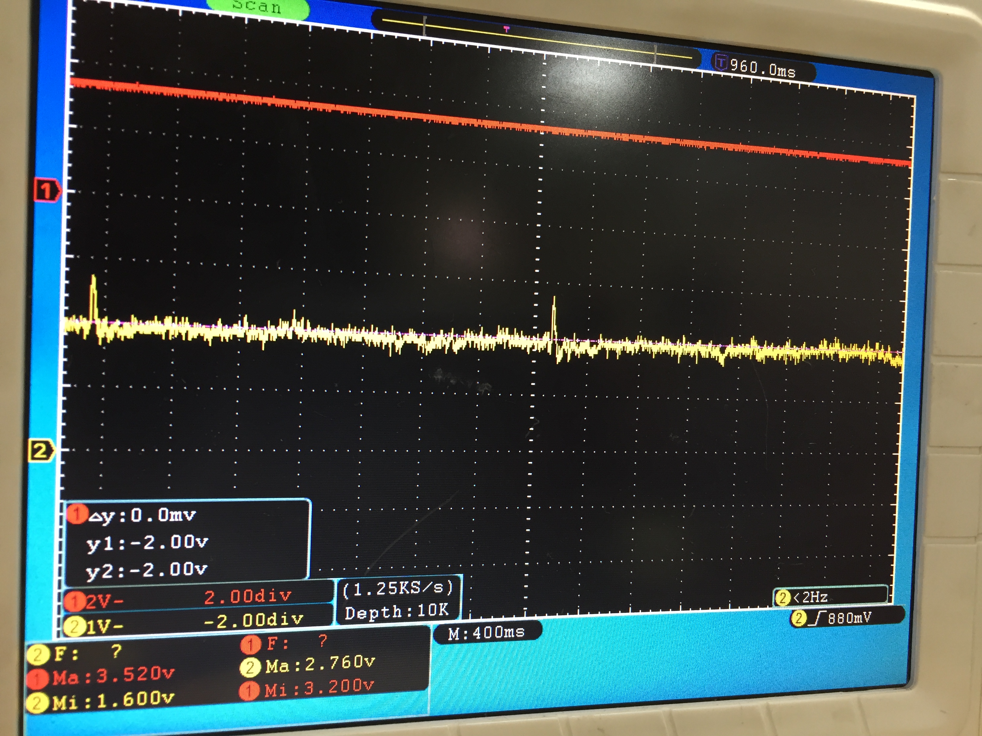
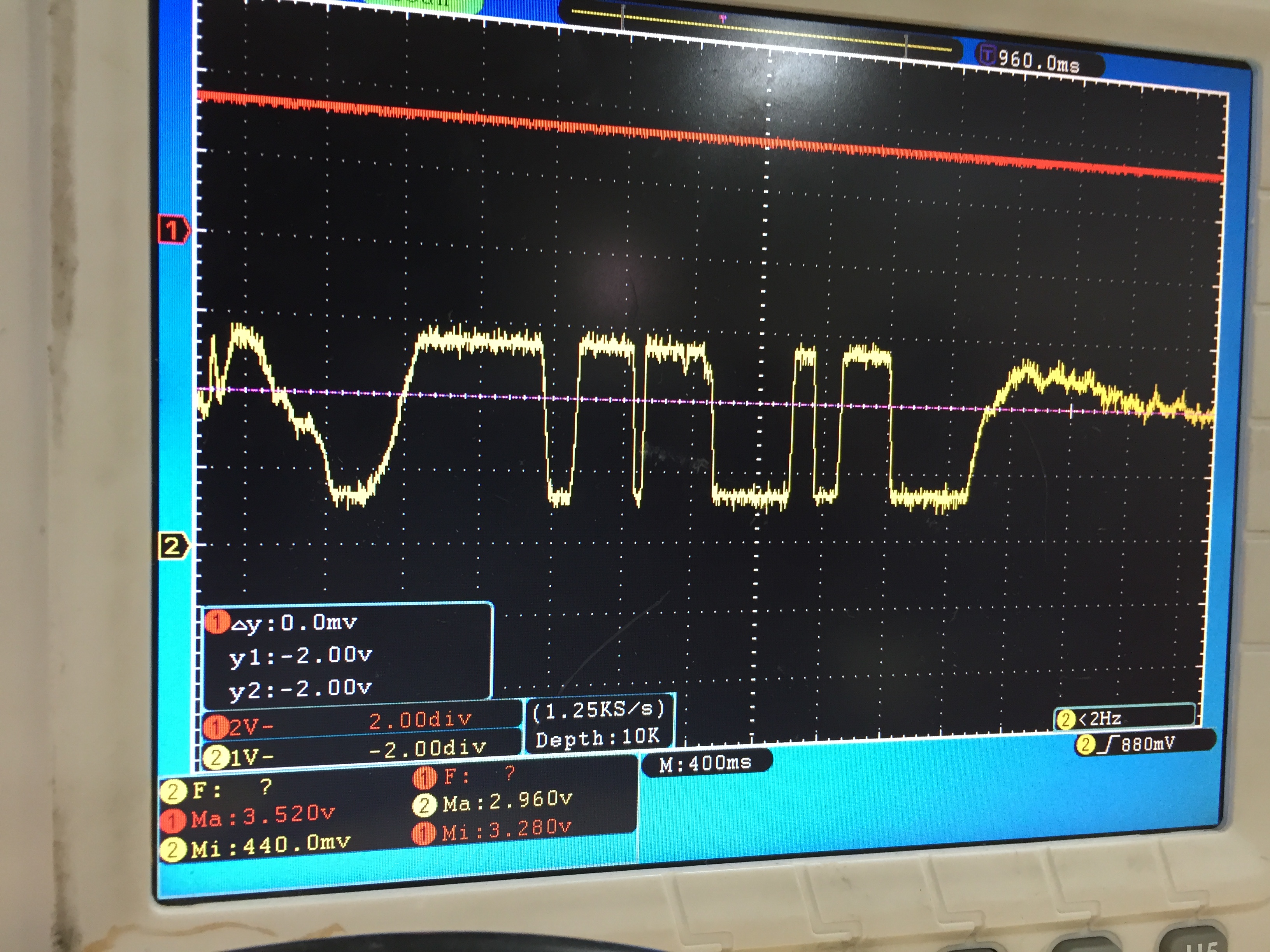
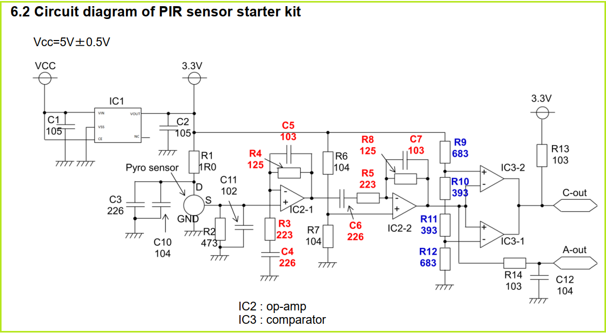
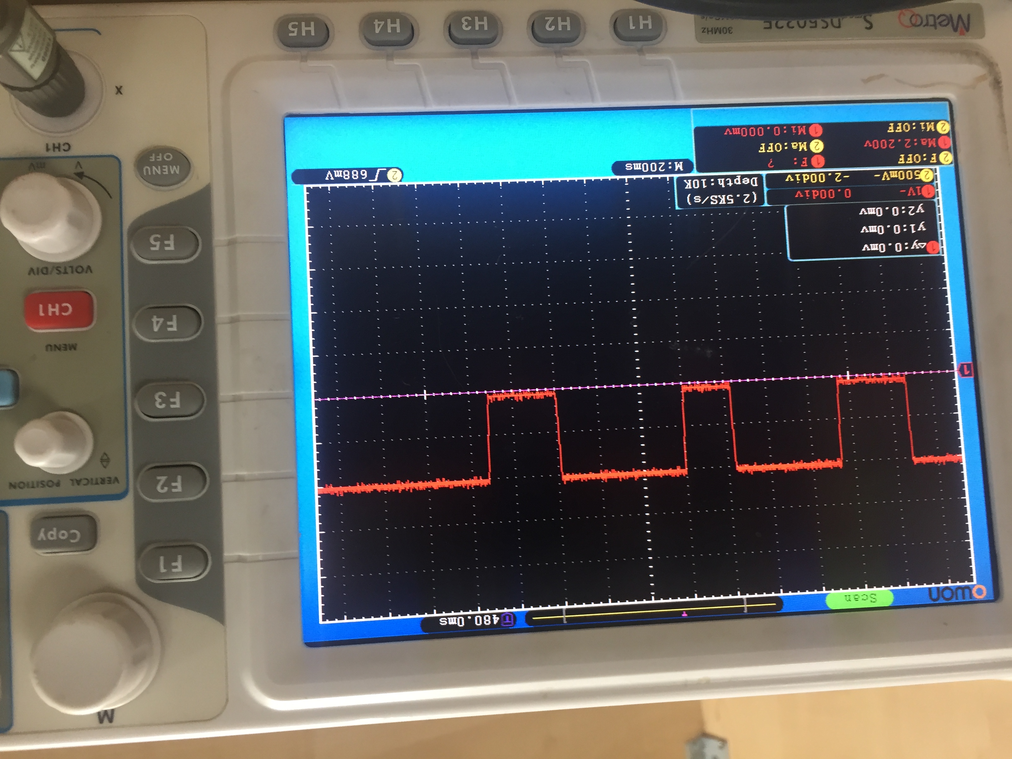
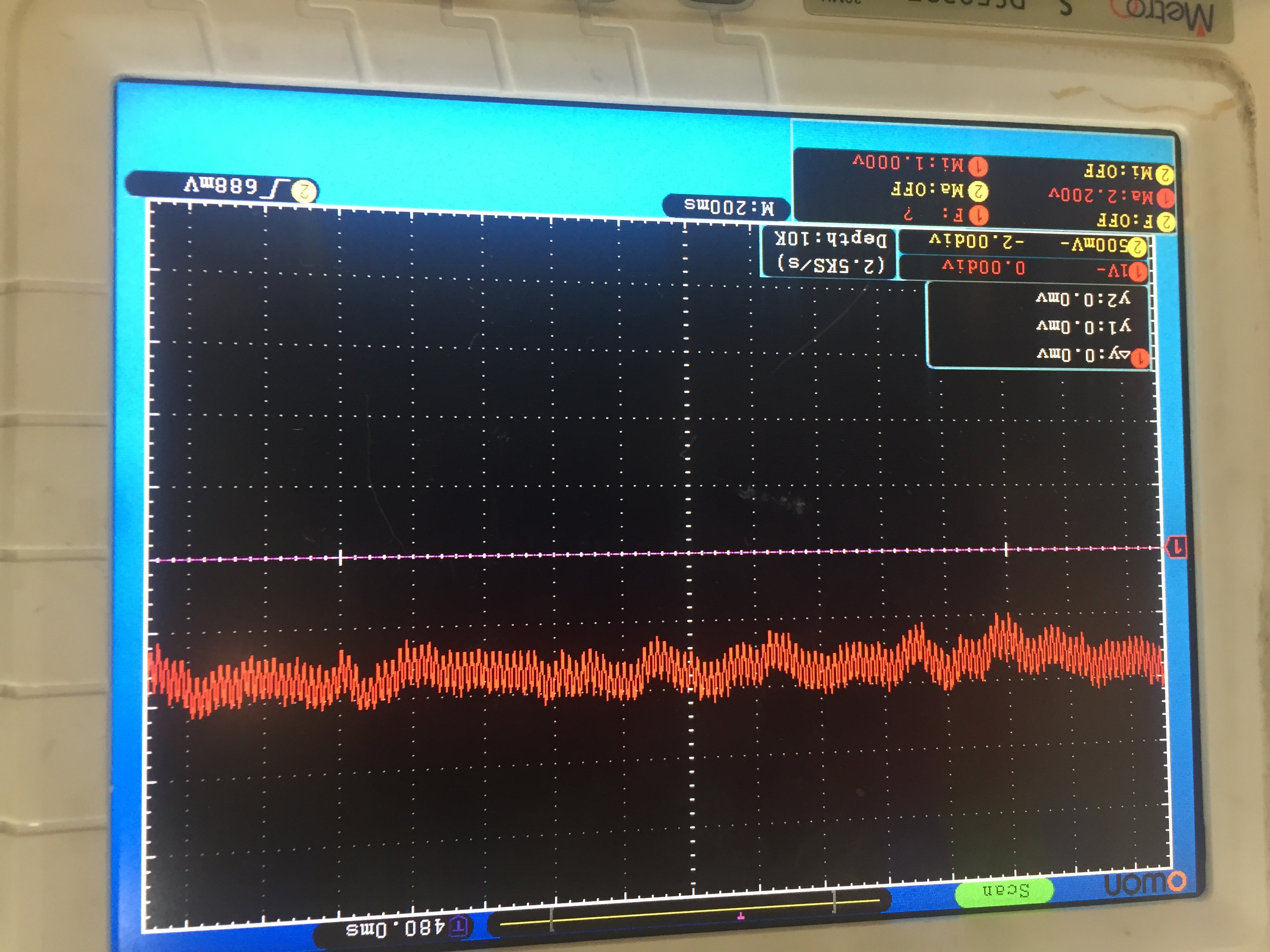
i am working with LM324 Quad op-amp for PIR sensor Sensor: IRA-S210ST01 Lens: IML-0685/0688 i get output without any movement detection, i don't know how to calibrate the sensor, i have attached my schematic for your reference, i was changed VR1 value is 1M ohm fixed resistor, then i was set VR# output volt is 1.2V and VR$ output volt is 3.1V,
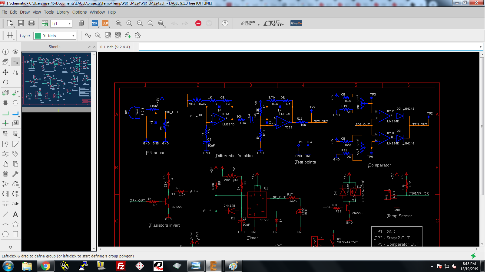
i don't know what is the problem here, kindly help to find what mistake i made in the schematic.
regards
kannannatesh
Hello Kannannatesh,
Refer to the reference design here. https://www.ti.com/tool/BOOSTXL-TLV8544PIR More steps were taken to filter out noise. Noise will be the main circuit concern.
Also helpful is http://www.ti.com/lit/pdf/tidueh9 , http://www.ti.com/tool/CIRCUIT060004 , and http://www.ti.com/lit/pdf/sbaa285
More filtering (add capacitors) is needed for PIR power, IC1B pin 5, IC1C pin 10, and IC1D pin 12.
Check each circuit stage with an oscilloscope looking for noise or any other unwanted signal.
thanks for your reply, I will go to order Ti booster pack board for reference from
https://www.digikey.in/product-detail/en/texas-instruments/BOOSTXL-TLV8544PIR/296-47036-ND/7563140?
it will be working fine for hole days then I will follow the footsteps for my design
regards
kannannatesh
Hi Natesh,
I would run a TINA-TI simulation of your circuit.
TINA-TI can be downloaded here and is for free:
You can even post your TINA-TI simulation file here then, if you need further help.
I would think about replacing the NE555 by the TLC555 because the CMOS-555 produces way less noise and interference.
Kai
Dear Kai,
thanks for your presence and I had found my mistake for anonymous output, filter(Capacitor) has done a major role in output, then i can't find another answer for another one problem my sensor working perfectly for more than one hour after that the sensor does not detect any movement it gives the high pulse continuously, i can't find what is the problem here and i was restart(on/off) the module for checking that gives same high pulse after that i switched off the sensor for ten minutes then switch on my sensor that's working fine, it makes confuse kindly help to find the solution for that issue. usually that sensor output before amplification it gives .6v to .8v that time the sensor working fine suddenly it gives greater than 2v that time the sensor does not detect any movement, i can't understand why the output voltage is suddenly increased.
regards
kannannatesh
Hi kai klaas69 and Ron Michallick
thanks for your suggestion, i have purchased BOOSTXL-TLV8544PIR for reference so i would check the board for a couple of days then i just follow the schematic for the design. then i have one doubt about BOOSTXL-TLV8544PIR and IMX-070 (Murata evaluation kit) these boars have a lot of holes in PCB why they are making a lot of holes? what is the use of that?
if i powerup the BOOSTXL-TLV8544PIR through our CC3320SF launchpad (System CPU power) it's working fine, then if i connect other power sources like mobile charger that are misbehaving like that is give output anonymously, what is the problem here
kannannatesh
Hi Natesh,
the holes are vias which connect the ground fills with the solid ground plane. This minimizes ground noise and improves the screening effect of ground fills.
You must power the board with a clean, noise free a stable supply voltage. A mobil charger is rather unsuited to power the board.
Kai
Hi kai klaas69
Thanks for your answer, the USB power supply Max volt is 5.280V to 5.320V and Min volt is 4.820v to 4.860v then LM2596 power supply module it gives Max5.040v to 4.960v Min 4.620v to 4.540v, what is the problem here
regards
kannannatesh
Ni Natesh,
I'm a bit confused now. Can you provide a drawing or sketch which shows what you exactly want to hook together?
Kai
Kannannatesh,
All switching regulators including LM2596 create noise in the power output, in the ground, and even in the air. With enough filtering and or linear post regulation the noise can be reduced. Maybe enough to work again.
Hi kai klaas69
I have attached my DSO output for your reference the RED line represents input voltage and Yellow represents the PIR 2nd stage amplifier output and also that image have a min&max voltage for those voltages
the power supply given by LM2596 board 5v then I have connected AMS1117 for 3.3v output. my problem is i have esp8266 for read analog voltage but if connect PIR 2nd stage analog output with esp8266 analog pin that shows no change it's automatically goes to low in the output i don't know what is the problem here,
i have another one doubt my schematic shown in the previous post that R12 is 1.5k and R13 is 1k but the BoostXl have 15M ohm for that if the lowest value make any problem in PIR output
Hi Natesh,
if you do not connect the PIR 2nd stage analog output to the esp8266 analog pin, does the PIR 2nd stage analog output work properly then? Can you confirm with the scope that the PIR 2nd stage analog output is properly working, when having the esp8266 analog pin disconnected?
The LM324 and the TLV8544 are totally different OPAmps. The LM324 has high input bias currents and needs low resistors to generate the "middsupply" reference. The TLV8544, on the other hand, has ultra low input bias currents and can tolerate resistors of much higher resistances in the middsupply voltage divider.
Again, have you noticed that the people from Murata recommend a different circuitry directly at the pyro sensor in their appnote?
Kai
Hi kai klaas69
my sensor is working fine but i have one issue this issue also occurs in BOOSTXL-TLV8544PIR board.
i have attached DSO output image for your reference i have power up the BOOSTXL-TLV8544PIR through LM2596 for 12 to 5v power supply then i have used AMS1117-3.3 linear regulator for getting 3.3V output, this power supply is connected with BOOSTXL-TLV8544PIR board 3.3V terminal
1st image shows output of when motion is detected and it gives 0V output and the output waveform is stable 0v to 2.2V but the second image shows noise output, the output voltage is not stable the image shows min(1V) and max(2.2v) voltage how can i reduce this noise from the output because my own design (I posted in the previous discussion) has same output noise problem, my guessing is maybe the power regulator is making noise, my guessing is correct or not?
if i am correct which regulator is best for this design?
i hope you understand my problem then kindly help to solve this out
regards
kannannatesh
Hi Natesh,
can you first answer my question, please? I repeat it again:
"If you do not connect the PIR 2nd stage analog output to the esp8266 analog pin, does the PIR 2nd stage analog output work properly then? Can you confirm with the scope that the PIR 2nd stage analog output is properly working, when having the esp8266 analog pin disconnected?
Kai
Hi kai klaas69
ya sure, now the device working fine after connecting with original node MCU board (esp8266) analog pin, that gives 700 to 400 analog value, i have changed the resistor value VR1 and R14 to 1Mega ohm and the App note Schematic have R3-22k and C4-22uf but my schematic have C2-10uf and R6-10K
i made one mistake in my schematic as per App note schematic C6 connect before the R5 but my schematic has connected C4 after the R10.
App note has R6 and R7 value is 10k 2nd stage (non-inverting terminal input) but my schematic voltage divider resistor(R12&R13) value is 1k.
kannannatesh
Hi kai klaas69
thank you very much for your support and suggestions finally I found the problem, in my first case i was powerup the module through LM2596 that is the problem that makes a lot of variation in output voltage that is the reason to get anonymous output from my sensor, now I am powerup my sensor through AMS1117-3.3V linear voltage regulator and I connect 2nd stage analog output to my ESP8266 and set the value is <100 now my sensor is working fine but i need a help to find perfect linear regulator for my design, I have to design PIR, Smoke, Temperature with ESP8266
regards
kannannatesh
Hi Kannannatesh,
happy to hear that you could solve most of the problems :-)
The LM2596 is producing lots of noise. You can try to add a post filter as shown in figure 32 of datasheet:
But I would try to replace all the switchers (LM2596) by linear regulators. Take a look at the LM78xx series. This regulators have become an industry standard since decades, are very nice and absolutely easy to use:
Kai
Hi kai klaas69
i have an LM2596 module that has the same as above you showed schematic so i think just go with LM340 (SOT223) what do you say?
regards
kannannatesh
Hi Kannannatesh,
yes, good idea!
For 5V output voltage this would be the LM7805.
Kai
Hi kai klaas69
As per Murata App note, they are powerup the sensor through 3.3v but the LM340 is given 5V output so what can i do now, if i choose TL1963A that makes my BOM cost is high kindly help to find low cost linear regulators that support wide range of input 4v to 15v input, output current is 1.5A
regards
kannannatesh
Hi kai klaas69
thanks for your suggestion it has sot 223 packages as per my need but I have one question about LM317, the regulator is given constant output voltage or it depends on the input voltage if my AC to DC adapter gives 10v to 14v then i connect with my LM317 (i designed 3.3V at 12v input as per datasheet) what is output voltage of LM317 it gives constant voltage or oscillating output voltage.
regards
kannannatesh
Hi Kannannatesh,
the LM317 needs two resistors to program the output voltage. See section 8.2 of datasheet.
Kai