This thread has been locked.

If you have a related question, please click the "Ask a related question" button in the top right corner. The newly created question will be automatically linked to this question.

INA143: Fault Protection of INA143

Part Number: INA143

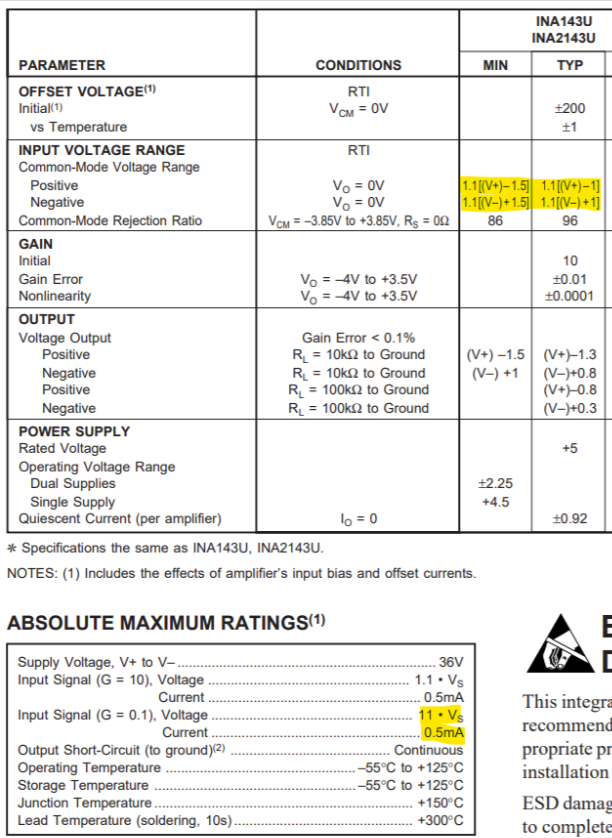
I have an application where I receive 20V RMS sine wave and I am planning to use INA413 to attenuate to 2 V RMS. Simulation works fine. I wish to see the impact on output, when power supply to op amp is turned off and inputs are applied. Will it damage the IC? Can we somehow check this effect in TINA?

  • Hi Gary,

    Thank you for your post, I can help you. The input pins must remain within a specified range according to the power supply pins in order to limit the current flowing into the amp. This is shown in the datasheet electrical characteristics table under input voltage range. The TINA model will not show this behavior.

    -Tamara

  • Hello

    I am particularly interested to know the impact , when power supply is switched off and inputs are still present.

  • Hi Gary,

    have you seen figure 6 of datasheet?

    What do you fear to happen?

    Kai

  • Hi

    In some devices clamp diodes used for power supply reversal protection can get activated during power off condition (and when inputs are applied). This can lead to large current flowing into the device and heating up. I was just concerned of a similar effect. In my application, I have a situation, where inputs (about 30V) may be applied to INA143 ( used as an attenuator configured as per Fig.6) under power off conditions. Please confirm to us with reasoning.

  • Hi Gary,

    if there are such protection diodes from the inputs pins to the supply rails, then they are always present. They don't become activated during power-off. They can only become conducting when the input voltage exceeds the supply rails.

    Why not measuring this current by yourself? Take the circuit from figure 6 of datasheet. Connect everything as shown there. Then connect the supply voltage pins to 0V and connect a voltage source to "Vin" (pin 1). Also put a current meter in series to the voltage source to be able to measure the current flowing into pin 1. Now increase "Vin" carefully and measure the current. As long as the current stays below 0.5mA (Vin < 50V), everything is fine.

    You can also measure the current flowing in and out of the supply pins by looping a current meter into their ground connections.

    Kai