This thread has been locked.

If you have a related question, please click the "Ask a related question" button in the top right corner. The newly created question will be automatically linked to this question.

UAF42: UAF42 Square Wave to Sine Wave Filter

Part Number: UAF42

Hi Team,

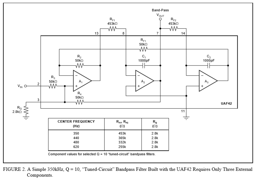
Our customer is designing a filter to generate sinewaves using the circuit in Figure 2 of SBFA003 application note. He need to determine the values of resistors RF1 and RF2 to produce 40.6Hz and 528Hz. He will create 2 separate circuits for each frequency. How can we compute for the values of RF1 and RF2?

Regards,

Danilo

  • Hi Danilo,

    haven't you seen the design equations in the datasheet?

    For 40.6Hz I get:

    RF1 = RF2 = 3M9201

    For 528Hz I get:

    RF1 = RF2 = 301k43

    See also the appnotes on the product page of UAF42:

    Kai

  • Hi Danilo,

    I did a quick UAF42 circuit simulation using the RF1 and RF2 values that Kai derived for 40.6 Hz and 528 Hz band-pass filters. RQ remained at 2.8 k. The results from a TINA Spice gain vs frequency sweep are seen here:


    Keep in mind that the resistors and capacitors internal to the UAF42 do have component tolerances so the center frequency (fc) can vary a little between devices. Use low tolerance precision resistors for RF1 and RF2 to minimize response variations caused by them.

    Regards, Thomas

    Precision Amplifiers Applications Engineering

  • Hi Kai and Thomas,

    Thank you for sharing the values of resistors for these requirements and for the confirmation thru simulation.

    Regards,

    Danilo

  • Hi Team,

    The customer is requesting for the formula used to find the values of RF1 and RF2. I used the formula of Noninverting Pole-Pair at page 6 of the datasheet but can't figure out how to arrive with these values.

    For 40.6Hz

    RF1 = RF2 = 3M9201

    For 528Hz

    RF1 = RF2 = 301k43

    Regards,

    Danilo

  • Danilo,

    Applying the equations listed in the UAF42 Figure 1. Noninverting Pole-Pair circuit and running the algebra for the band-pass here are the results:

    First use Eq. 6 to set band-pass gain:

    ABP = R4/RG   

    and since RG = R4 , ABP = +1V/V

    Then to find RF1 = RF2 it is derived From Eq. 1:

    RF1 = RF2 = [1 / ( 4π2∙fC 2∙C12) ] 0.5

    For example if fc = 40.6 Hz

    RF1 = Rf2 = [1/ ((39.48) (40.6)2 (1∙10-9)2) ]0.5 = 3.92∙106

    The same value that Kai provided.

    Regards, Thomas

    Precision Amplifiers Applications Engineering

  • Hi Thomas,

    Thank you for these information. The value of RQ is 2.8kΩ in the application note. Should the customer maintain the value of RQ for 40.6Hz and 528Hz?

    Regards,

    Danilo

  • Hi Danilo,

    the UF42 implements the so called "state variable filter". One of its advantages is that the frequency of operation and the Q factor can be varied independently. So, if you still want a Q=10, then there's no need to change the RQ=2k8 resistor.

    Kai