This thread has been locked.

If you have a related question, please click the "Ask a related question" button in the top right corner. The newly created question will be automatically linked to this question.

LM6172: simulating LM6172 + CSD19534Q5A in Tina - questions about the models

Expert 6310 points
Part Number: LM6172
Other Parts Discussed in Thread: CSD19534Q5A, TINA-TI, OPA2690, THS3122

Team,

we worked with LM6172 simulation for a while to have the noise simulation also working.

Can you please help to check / validate our simulation? Link: LM6172_CSD19534Q5A.zip

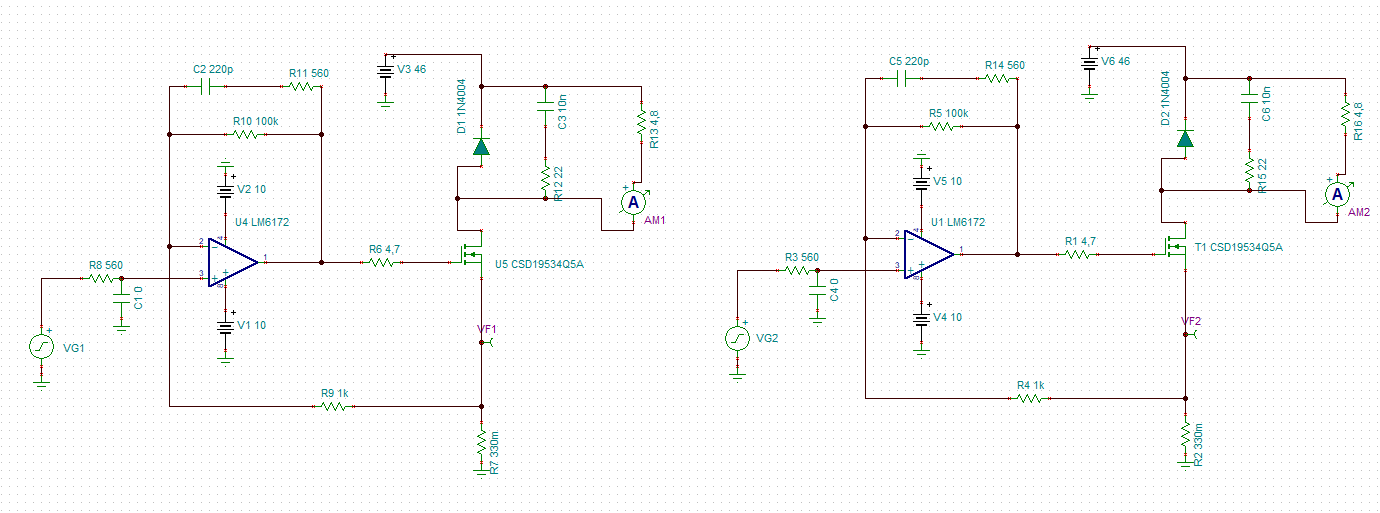
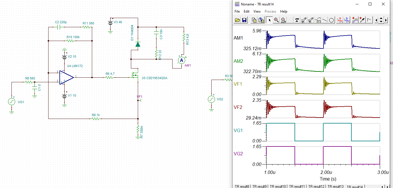
1) Output_mos_LM6172_CSD19534Q5A_ref.TSC , we used: 

LM6172 -> Spice Macro within Tina-TI

-> downloaded slpm324.zip CSD19534Q5A TINA-TI Spice Model


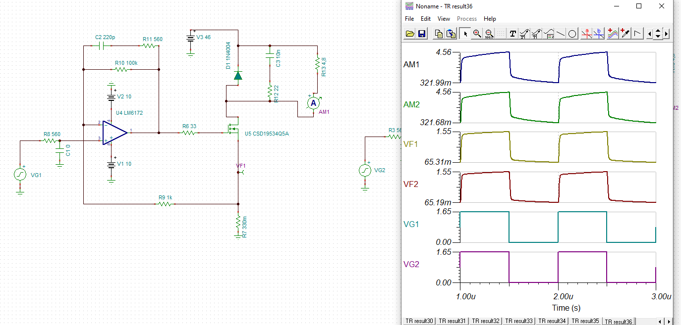
2) Output_mos_LM6172_CSD19534Q5A_PSPICE.TSC, we used:

LM6172 -> Spice Macro within Tina-TI

CSD19534Q5A -> downloaded slpm119a.zip CSD19534Q5A PSpice Model  and imported to tina-TI


3) There are two models of  CSD19534Q5A on web page with different release date as mentioned above in two simulations:

a) Are the two models the same, or is one better than the other?

b) Do these model the Qg, Qgd, Qgs? Or rather Cgs, Cgd?


4) Regarding LM6172:

a) there is a model in Tina-ti for it - is this the same model as on the web page snom234.zip?

b) can you provide the latest model that you have?

c) Do we have a drop in replacement that has similar price performance ratio?

  • Without looking too closely at your specific requirements, I will say 

    1. The dual LM6172 is on an older slower process that supports 30V total supplies - if you don't need more than 12V there are much more power efficient options

    2. This is high slew rate VFA unity gain stable - that topology has the highest input noise - if you want low noise, this is not the way to go. 

    3. If you want this topology and can use a 12V max supply part (total) the OPA2690 is an option

  • Hi Michael,

    Thanks for your inputs. LM6172 is a solid balance between cost and performance for the specifications that we need. We'll take into account your note regarding input noise, as well as  consider OPA2690 as an option where we have narrower Vin requirements.

    Are you able to help having a look at the simulation attached above?

    Any feedback on our remaining questions?

    Thanks

  • Yes I got the TINA file imported, I get an irregular circuit error so far, can't see it though - stuck at this point, 

  • Hello Bart,

       For the 1st, 2nd, and 3rd question, I would have to ask the team who owns CSD19534Q5A, but I believe it is best to use the latest model (2020 version) and import it into Tina-TI as you have done in the second one. I will let you know what they say sometime early next week. For question 4, I would always suggest downloading the model from the website; since, that is going to be the most updated version. As Michael mentioned, there are not really any drop-in replacement for the LM6172, but there are other newer and improved parts with the same package but with varying specs. We would need more information on what specifications you are targeting when it came to choosing the LM6172.

    Thank you,

    Sima

  • Hi Sima,

    I will try to explain where is the catch with the OpAmp and why we want to do first the simulation with LM6172.

    We chose CSD19534Q5A transistor, and we need to choose the OpAmp that drive the gate of the CSD19534Q5A fast, meaning when we turn on the MOSFET, we have to have so that the defined current ID through the mosfet goes from 0A to defined value in around 1us.

    We are driving a string of LEDs, that are connected through a cable to our device.

    In the simulations that I attached in first post, we model this with a simple resistor but that is not real life, and when choosing an opamp this needs to be taken into account, that's why we used THS3122 opamp in the past. 

    1) I can't find what is the best way in tina-ti to model a 30m cable ? I tried to add only L in series but then the simulation doesn't match our measurements on the device.

    2) I also can't find how can we model a e.g 12 LED in series LCW MVSG.EC?

    So to answer your questions:

    We can also choose other OpAmp , but it needs to drive  CSD19534Q5A and meet the 1us requirement.


    What we see as important parameter of the opamp.

    a) Drive output current, to fast drive the gate charge of the  CSD19534Q5A

    b) reasonable GBW, currently we have here 100x gain, so effective BW of LM6172 is GBW/100 = 1MHz

    c) we see that both LM6172 and THS3122 have high slew rate, but currently I'm not really sure how this affects 1u requirement

    We can also go with lover voltage supply of the opamp if this will satisfy our needs this is why we do the simulations, but we would like to have the OpAmp supply to be ± some voltage because we want also to have fast transition when the transistor closes.

    I think our simulation that I provided is a good starting point, but we first need to know how to model the LED and cable.

    Looking forward for your feedback.


  • Hello Bart,

        Thank you for all the details. 

       1) Yes, we usually just add extra inductance/capacitance/resistance as the parasitic impedance from PCB and/or wires. But if you would want a more accurate method to calculate these values: try checking out this link: https://e2e.ti.com/support/tools/sim-hw-system-design/f/234/t/472373?How-to-add-a-long-cable-to-a-simulation#pi320995filter=all&pi320995scroll=false

       2) I could not find a Pspice model for the LCW MVSG.E. So, the best next thing would be to choose any LED diode in Tina-TI, right click on it, and select properties. In the type section, there is a button next to the input element which contains three dots, click that and you can enter in the values matching the LEDs you need to drive. 

       3) In this application you described, you would be concerned about capacitive loading and how fast can the amplifier track changes at the input voltage. So, yes then GBP and, in a sense, slew rate will be your top concerns. There are a lot of amplifiers with high GBP and slew rate; here is a list: device list.

    Thank you,

    Sima

  • Thank you Sima,

    this helps.

    Last thing - have you been able to check/run the simulation model we asked about (LM6172_CSD19534Q5A.zip) - how can we validate if it's OK?

  • Hi Bart,

    these are my simulation results:

    Output_mos_LM6172_CSD19534Q5A_ref_kai.TSC

    And...

    Output_mos_LM6172_CSD19534Q5A_PSPICE_kai.TSC

    I think increasing the gate resistor from 4R7 to 33R will considerably increase the stability:

    Kai