This thread has been locked.

If you have a related question, please click the "Ask a related question" button in the top right corner. The newly created question will be automatically linked to this question.

TLV2452: Photodiode Amplifier Temperature Compensation

Part Number: TLV2452
Other Parts Discussed in Thread: OPA2340

Dear Ti Analog Team.

I'm designing a lux meter for streets lamps mesurement application. 

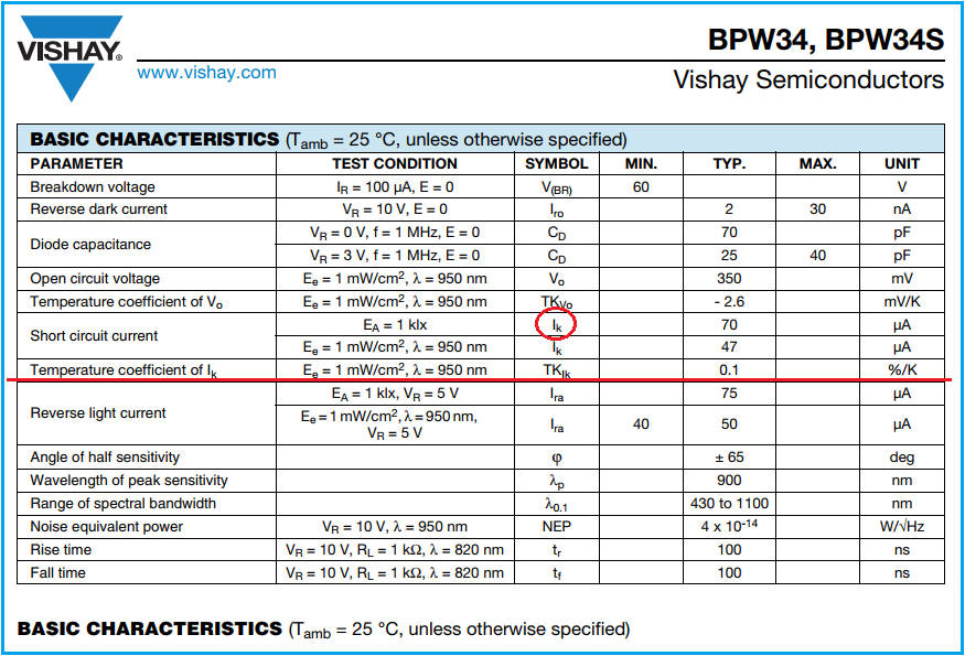
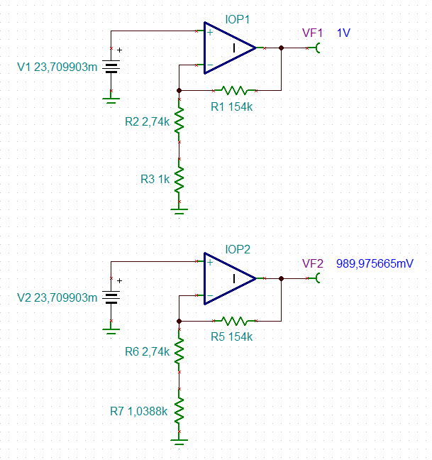
 I have Vishay photodiode BPW34  (http://www.vishay.com/docs/81521/bpw34.pdf) and TLV2452 as mounted at attached circuit. I'm concerned about temperature diode behavior, I did some calculation and got 1% variation at outpu to 10C temperature variation,  sensor will be expost at free  enviromet that temperature will be around  + 6 °C a 42 °C.  Could you please sugest a circuit to compensate photodiode temperature variation?

Thanks

Nuncio

  • Former Member
    0 Former Member

    Hello Nuncio,

    Thank you for your question and welcome to the forum!

    I would like to ask, is your calculation based on the diode alone?  Do you expect the diode's variation over temperature to dominate the variation of the resistor over temperature?

    My first reaction would be to suggest that you explore using a temperature dependent resistor, something as linear as possible, and put it in series with the feedback resistor.  I'd pick something with a small nominal resistance so that the 100k feedback component still dominates the response.  My concern with this approach would be that the resistor might not be linear enough to provide the needed accuracy, that the response curve might be too steep, or that it might not be steep enough.  Furthermore, this component would also be subject to process variation.  Depending on how bad this variation might be, it may even require each circuit to be manually tuned, which would be undesirable.

    What do you think of this approach?  I think it might be too crude for your accuracy requirements, but it is a thought.  If you don't like it, we can try to come up with something else.

    By the way, there are several TI resources for designing transimpedance amplifiers with photodiodes.  You may find this useful if you need help preventing instability in your circuit.  Here is a useful Burr-Brown app note on the subject.  Here is a cookbook circuit.  And finally, here is a reference design.

    Finally, if you are interested in potentially picking a different part, let me know.  It seems that the TLV2452 is especially designed for low current noise.  But, perhaps you'd be interested in an amplifier with different specifications.

    Regards,

    Daniel

  • Hello Daniel,

    Thanks for the prompt answer. Calculation was based on the photodiode alone, photodiode temperature dependency  is my main concern. 

    I'm looking to find a way to compensate diode response due temperature variantion.

    Resistor compensation is really clever solution, I like the idea. I will look at resistor behavior to check it will cause some errors.

    I check the TI resources that you send me I like the OPA2340, I believe that will fit well for this design.

    Thanks a lot and my best regards.

    Nuncio

  • Hey Nuncio

    I suspect you are trying handle dark current tempco, using a compensating resistor will not match that well and also vary your gain. 

    If your light source has an AC component, you could focus in that frequency range (50H, 60Hz) and AC couple the 2nd amplifier perhaps. 

    If the desired signal is truly DC, maybe a 2nd dummy detector diode feeding the current into the input node might cancel the DC part? 

  • Dear Mike thanks for the answer, desired signal is trully DC.   Do you think circuit bellow could work well?  Please let me know.

    Thanks 

    Nuncio

  • Hi Michael, hi Nuncio,

    I think it's the temperature drift of signal current of photodiode what Nuncio is talking about:

    The dark current should be rather low at a reverse voltage of VR = 0V.

    Kai

  • Hi Nuncio,

    I would compensate it with a PT1000.

    Kai

  • Dear Kai,

    Thanks for your answer, please send me your sugested draft circuit, I will simulate to compare results.

    My best regards.

    Nuncio

  • Hi Nuncio,

    I would do it this way:

    nuncio_bpw34.TSC

    R3 and R7 plays the role of PT1000. This circuit should replace your second OPAmp on the right of your schematic. The gain was increased by a factor of ten to keep the additional supply current small and to prevent self heating of the PT1000. To compensate for this additional gain you need to decrease the transimpedance by a factor of ten. Or put a voltage divider in front of this OPAmp circuit.

    Don't forget to put a small cap in parallel to RF. This will increase the stability of the first OPAmp at the left of your schematic by restoring the phase margin.

    Kai

  • Hi Nuncio,

    maybe like this:

    bpw34_temp_1.TSC

    Kai

  • Dear Kai,

    I like very much your solution,  Thanks a lot for the help.

    My best regards.

    Take care.

    Nuncio

  • You are welcome :-)

    Kai