This thread has been locked.

If you have a related question, please click the "Ask a related question" button in the top right corner. The newly created question will be automatically linked to this question.

MULTI-CAL-SYSTEM: PGA309 Test Board for Multi-Cal-System

Part Number: MULTI-CAL-SYSTEM
Other Parts Discussed in Thread: PGA309, PGA309EVM-USB,

Since there is not a PGA309 Test PCA available for the Multi-Cal-Sytem, is there any way to connect the PGA309 test board from the EVM kit to the multi-cal system so that I can use the PGA309 Multi-Cal Software?  

Alternatively, if I just connect the PGA309 EVM Kit, will I be able to utilize the PGA309 Multi-cal Software? 

  • Hi Patel,

    If you are interested on only testing one sensor, the PGA309EVM allows you to perform calibration of a real external sensor using the PGA309EVM-USB.

    The software of the Multi-Cal system is not compatible with the PGA309EVM USB since these are different sets of hardware.

    It is possible to adapt the PGA309EVM-USB Test Board to the Multi-Cal system but requires some work. 

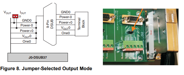
    The Multi-Cal interface card only requires the GND0, Power-, Power+, Vout, and One connections to the test card as shown below. 

    Multi-Card Interface Card Required Connections to Test PCA:

    For example, in voltage output mode, 4 screw terminal connections are required: 'GND', 'Power+', 'Vout', and 'One'

    This could be connected to the PGA309EVM-USB Test board: GND test point, VS1 test point, VOUT strip connector T3, and PRG test point. 

    One difference between the PGA308EVM-USB and the Multi-Cal-system, is that the EVM-USB uses the controller DACs and circuitry to emulate the bridge and temp sensor signals, while the MULTI-CAL test card uses either an external sensor or  voltage divider circuitry with jumpers to emulate the min/max bridge signals.

    One possibility is to use the Sensor-Emulator-EVM to externally generate the bridge signal and the diode or series resistor bridge sensor temperature monitor, and in this manner emulate the sensor signals. 

    On the PGA309EVM_USB card, the bridge signals would connect through strip connector T4 (Vin1,Vin2), the bridge sensor excitation (Vexc) and GND would connect to strip connector T2, and the diode or series bridge temp monitor through strip connector T5.

    Thank you and Regards,

    Luis 

  • Great thanks! I'll check this out and give it a try!