This thread has been locked.

If you have a related question, please click the "Ask a related question" button in the top right corner. The newly created question will be automatically linked to this question.

OPA140: There are two different OPA140 tina simulation files and the results are very different

Part Number: OPA140
Other Parts Discussed in Thread: TINA-TI, OPA365, THS4551, LMP7731

Hello,

I'm using OPA140 for tina simulation but there are two different opa140 spice files.

and simulation results are very different. which one is true?

simulation files are in tina library and in sbom430c.zip

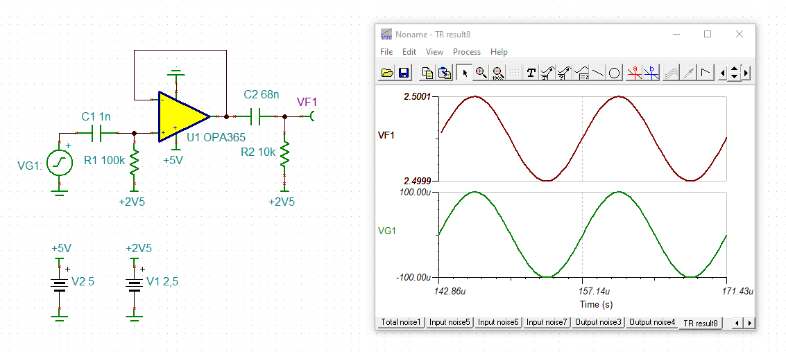
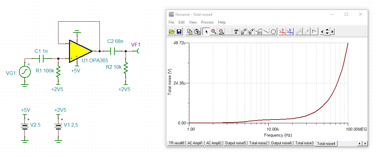
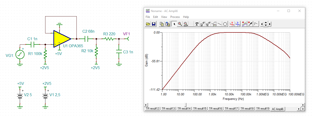
I put them in the same simulation circuit, please can you check it?WhichOneOPA140.TSC

  • Please run transient mode for 1ms

  • Hello Aykut,

    It looks like the TINA-TI op amp selection under Spice Macros hasn't been updated in quite some time. The one listed there is the original simulation model from 2011. It uses an earlier version of TI's sophisticated behavioral op amp model. SBOM430C.zip is the newer OPA140 model just updated in 2019. It is similar to the 2011, but with further enhancements made to the model. That is the model to use for most accurate results. 

    I do observe the differences obtained from the transient analysis with the two OPA140 model versions. Note however, that there is a setup problem with your circuit. The OPA140 is powered by a single +5 V supply, and the common mode voltage is +2.5 V. See from the OPA140 datasheet Electrical Characteristics table that the Common-mode voltage (VCM) range is (V–) – 0.1 to (V+) – 3.5 V, for TA = –40°C to 125°C. If V+ is 5 V, then the upper VCM is (V+) - 3.5 V, or +1.5 V max. The high end VCM is being exceeded a volt. Increasing V+ to a level where the high end VCM is no longer being violated should correct the circuit.

    If you need to operate with a single +5 V supply TI has many precision low voltage op amps that have a VCM range from (V-) - 0.1 V to (V+) + 0.1 V. We can help you select the most appropriate low voltage op amp if needed.

    Regards, Thomas

    Precision Amplifiers Applications Engineering

  • Thank you Thomas.

    I couldn't notice VCM range because of the different results. I need a ultra low noise buffer op-amp for the same circuit. I'll be glad, if you help me.
    I will use it between 40Khz-80Khz as unity gain/buffer. VDD=5V, VCM=x

    I tested some op-amps that are low input voltage noise and low input current noise density and found Opa365 that is best low noise for 70khz in tina.

    Can you suggest me another op-amps?


    Regards,

  • Hi Aykut,

    to find the latest model of OPAmp, go to the product site of OPAmp and open the "TINA-TI Reference Design". Draw your circuit in this reference design or copy and paste the model into your circuit.

    aykut_opa365.TSC

    But the total noise is a bit high because the OPA365 has a wide bandwidth:

    A simple low pass filter at the output of circuit can decrease the HF noise:

    aykut_opa365_1.TSC

    Kai

  • Dear Kai,

    thanks a lot for your help

    My circuit structure is buffer, preamplifier(THS4551) and narrow band BPF(THS4551). I added the tina file and picture without BPF.

    Buffer and preamplifier has wide band and I want to add low pass filter between buffer and pre-amplifier like you.

    But differential pre-amplifier includes low value resistors for low noise and low pass filter too so I don't want to reduce the signal level too much

    how should I put low pass filter in circuit?  

    AU_Pre.TSC

  • Hi Aykut,

    can you tell a bit more about your application? Where is the input signal coming from? And what do you want to connect to the output of THS4551?

    Kai

  • I want to read an hydrophone signal

    hydrophone -> Buffer -> preamp(ths4551) -> 4.th BPF(THS4551) -> VGA -> ADC

    by the way, I added parallel 22-47pf to gain resistors in preamplifier, but not effective.


  • additionally , VGA or BPF, whichever comes first, I'm undecided.

  • Hello Aykut,

    Since this is a low voltage, low noise application I suggest the LMP7731 bipolar op amp. Its Input Referred Voltage Noise Density at f = 1 kHz, and VCM = 4.5 V is typically 2.9 nV/√Hz for 5 V supply operation. It is usable with supply voltage down to 1.8 V, and has a 22 MHz GBW which should nicely meet the requirements of your 40 to 80 kHz application.

    The LMP7731 provides the best noise performance of any of our low voltage Precision Amplifier op amps. You can find more information about the LMP7731 on its web page:

    https://www.ti.com/lit/ds/symlink/lmp7731.pdf

    The OPA365 is supported by TI's High Speed Amplifier product group. If you decide to move forward with the OPA365, please use their e2e forum for best assistance.

    Regards, Thomas

    Precision Amplifiers

  • Hi Thomas,

    thank you for your suggest.

    i am asking to learn,  LMP7731, why I couldn't understand better than opa365?  Please tell me where I made a mistake

    yes, LMP7731 has low voltage noise density than OPA365 but its current noise density is a little bigger. (1.1pA > 0.8fA )

    input impedance of my circuit (100K) is big value so current noise density is more dominant.

    in simulation

    total noise with opa365 : 117uV ( with 40dB gain)

    total noise with LMP7731: 153uV ( with 40dB gain)

    plus, I will amplify the signal 60db with VGA. (total 100dB) so

    under these conditions, VGA is saturated earlier by noise of the circuit that includes lmp7731 buffer. I'm wrong?

    thank you in advance

  • Hello Aykut,

    The OPA365 resides with TI's High Speed Amplifiers Product group. When addressing op amp applications my thoughts gravitate to our Precision Amplifiers products which I am most familiar with such as the LMP7731, etc.

    Certainly the CMOS OPA365 will have much lower current noise than the bipolar LMP7731 and that could be a deciding factor when the source impedance is very high. When I review the OPA365 buffer stage that precedes the FDA stage I see that it is ac coupled to the signal source, and VCM is provided by the 100 kilohm resistor connected to the +2.5 V source. Even though the signal source impedance is on the other side of the input coupling capacitor from the 100 kilohm VCM bias resistor, as the frequency increases and the capacitor's reactance decreases the source impedance and resistance are more so in parallel. Therefore, the op amp input current noise flows through both paths. More and more of it flows through the source impedance (provided it is a much lower impedance) vs. the 100 kilohm resistor as frequency increases.

    I set up your input buffer circuit for both the OPA365 and LMP7731 and ran Input Noise and Total Noise simulations. Both op amp models model voltage and current noise densities. The results can be seen for each of the two op amps. The OPA365 circuit output is Vo1, and the LMP7731 circuit output is Vo2. If the buffer circuit is indeed as seen in a previous post, then the LMP7731 provides overall lower input referred voltage noise and total noise. The OPA365 would have slightly lower 1/f noise below 2 or 3 Hz, and total noise below 10 Hz.

    If the circuit is different than seen and the input current noise is only flowing through the 100 kilohm resistor, then the current noise of the LMP7731 will dominate and better noise performance will be obtained from the OPA365.

    Regards, Thomas

    Precision Amplifiers Applications Engineering

    LMP7731_Hi_Zsource_noise_02.TSC

  • Hi Thomas,

    I got it thank you,

  • Hi Aykut,

    can you increase your C1?

    Kai

  • Hi kai,

    I changed the buffer IC and some components (c1 also) so noise decreased about 5-6db.

    thanks a lot.