This thread has been locked.
If you have a related question, please click the "Ask a related question" button in the top right corner. The newly created question will be automatically linked to this question.
I am working with three OPA549T devices. Each is fed with a 10Vrms, 400Hz input and requires an output up to 5.00Arms at 10Vrms. Current is limited to 8A for each amplifier. The op-amps are supplied with +/-15VDC rails. There is a 247 CFM fan cooling the op-amps.
I think the performance issues I'm having come down to the incorrect heat sink size and poor thermal compound between the case and heat sink, but I want to make sure that I'm not missing something.
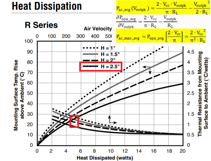
My worst case Power Dissipated, with the load a peak current of 1.6 Ohms, is (15V)^2/1.6 Ohms * 0.2 = 28.125W.
I am currently using RA-T2X-25E heat sinks from Ohmite. I think I need their RA-T2X-64E.
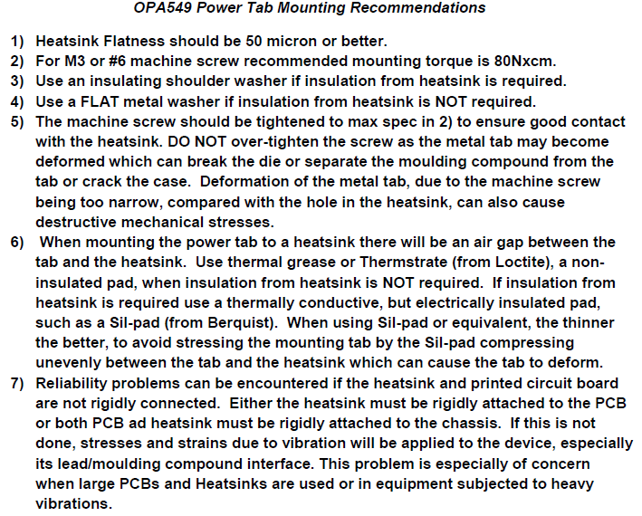
The thermal pad available was a poor choice, they are 175-6-220P pads from Wakefield-Vette. They don't cover the full case-to-sink interface and don't conduct heat as well as required; I think I need better than the 0.40 C/W thermal resistance of those pads.
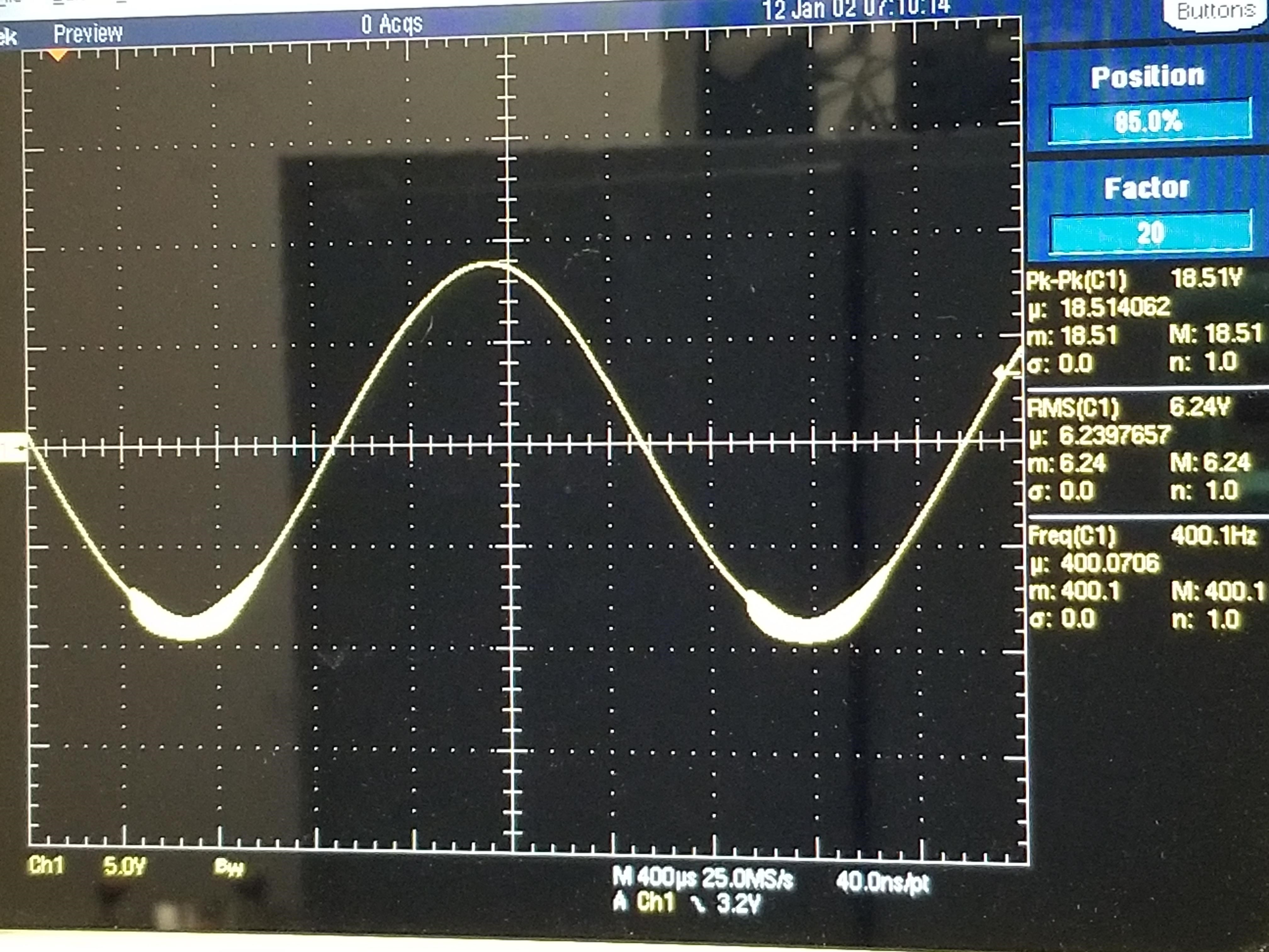
Attached is an image of the behavior seen at the 5.00Arms load. I'm outputting about 4.00Arms with the imaged waveform.
Beyond the obvious issue with the thermal pad, are there considerations I'm missing to resolve this performance issue? Would there be a benefit to adjusting the supply voltages to the op-amp? Do you agree that a larger heat sink is required?
Hi Zachary,
It looks like that you need the larger heat sink, RA-T2X-64E, based on my calculation. The OPA549 is running an average power of 28.5W, If I take your flow rate of 247 CFM, the heat sink dissipation plot is shown approx. 0.9 C/W, make is 1C/W. This will raise the OPA549's junction temperature to approx. 25C + 28.5*1C/W + 0.4C/W*28.5W = 65C. This figure is the minimum temperature rise in the junction temperature, and the actual figure may be slightly higher than that.
If you lower the supply's voltage rails somewhat (only reduce by +/- 1V, see output voltage requirements on p.3 of the datasheet), it may reduced the overall heat dissipation, see the average power dissipation equation in yellow in the image below.
If you use better thermal conductive pad, it will also help to reduce the overall junction temperature. In addition, please see the torque requirements for OPA549.
From the scope shot, I saw some oscillation on the negative rail. Are you able to share the schematic with us? If unable, you may send me a friendship request via E2E, and you can send me the schematic through a private email. I'd like to take a look at the Tina Simulation. What was the OPA549 driver's application?
Best,
Raymond
Hi Raymond,
I'll send you a friendship request to share the requested information. I think it's safe to rule out torque as an issue. When the boards in use first arrived, the OPA549Ts were either faulty or damaged during assembly, and I confirmed with the manufacturer that the faulty and new parts were installed with correct torque levels when getting the amplifiers replaced.
Glad to hear we're on the right track so far, I'll be able to send you more information privately.
V/R,
Zach Pinz
Hi Zach,
an analog power amplifier shows the maximum heat dissipation at 50% square wave, in your case 7.5V^2 / 1.6R = 35W.
Yes, I agree with Raymond that the cooling should be improved. Take care, the numbers with the fan cooling are only valid, if each heatsink has its own fan. And the ventilation must not be hindered by the enclosure. So, regarding the cooling you need to provide lots of headroom.
Kai