- Ask a related questionWhat is a related question?A related question is a question created from another question. When the related question is created, it will be automatically linked to the original question.
This thread has been locked.
If you have a related question, please click the "Ask a related question" button in the top right corner. The newly created question will be automatically linked to this question.
Hi Team
I have read the topics related to paralleling the OPA549 and plan to use this design in order to build a V/I converter connected to an Arbitrary signal generator in order to generate a current shape with 25Apk and a width of 15ms. So we are clearly in an impulse power load on the OPA549, so I would be interested in the thermal model to simulate the Junction temperature during the pulse, and dimension accordingly the thermal mass needed on the case to limit the junction temperature.
Thanks for your support
Christophe
Hi Christophe,
I would be interested in the thermal model to simulate the Junction temperature during the pulse, and dimension accordingly the thermal mass needed on the case to limit the junction temperature.
Could you send me the schematic of V/I converter that you are working on?
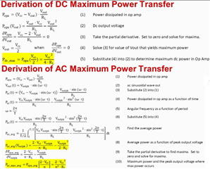
I will be happy to provide the simulation of the thermal calculation in Tina, but I need to have the schematic. All of our amplifiers are able to extract these thermal figures, but it depends on the supply rail, quiescent current, output current load and voltage etc. Enclosed is equations that are used to calculate power transfer in DC and AC in amplifier.

build a V/I converter connected to an Arbitrary signal generator in order to generate a current shape with 25Apk and a width of 15ms.
Regarding to the application, paralleling power amplifiers may be an option, but it may not be a feasible one for the peak current load of 25Apk. There are other options that you may do some research to construct the V-to-I converter. Enclosed are two application notes that you may be interested in. We have more similar application notes in our website as well.
I would the recommend the second option in slau502 application note. If the driver requires source and sink in 25Apk, then the design has to feed back the output signal differently, but the application note should point you in a right direction. It will also good to provide an approx. budget of the project and design requirements (e.g. how accurate the current source needs to be).
Please let us know if you have other questions.
Best,
Raymond
Hi Raymond
Thanks for your suggestion of a current source like in SLAU502. Seems less complicated than using multiple OPA549 in parallel.
I will simulate this solution and come back to you in case of problems.
I think you can close this topic.
Regards
Christophe
Hi Christophe,
Seems less complicated than using multiple OPA549 in parallel.
Yes, this is correct. By paralleling OPA549s, you need at least three op amps, and typically we would recommend to parallel two power amplifiers together. The output stages by paralleling multiple op amps together tend to "fight" for sourcing/sinking current among op amps, because these are not perfectly matched. You have to insert Riso resistors at the output stage in order to stabilize the control loop.
With SLAU502 feedback loop design, you may move the heat generated components to BJT or MOSFET, and you may use a precision op amp if you to want to keep the pulse current accurately. Please make sure that the feedback loop is stable for the driving application.
If you have additional questions, please let me know.
Best,
Raymond