This thread has been locked.
If you have a related question, please click the "Ask a related question" button in the top right corner. The newly created question will be automatically linked to this question.
Dear expert,
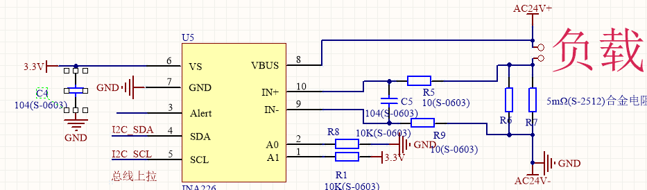
My customer is using INA226 to sample the power in 24Vac(50Hz), 8A load system. Please help to review the schematic and share your suggestions. BTW, IN+ and IN- seems can be connected to AC signal, but can VBUS be connected to 24Vac directly? Thanks.
Hi,
One compliment here. Customer are using INA226EVM to test, but they found when apply 24Vac to Vbus, the IC seems like damaged and can't communicate with host. So I'd like to confirm whether our IC can measure the AC power.
Hey Minqi,
Thanks for the update. Yes, the INA226 cannot measure AC power directly. In the schematic, the VBUS pin is connected directly to the power source and thus during the negative cycle will see a -24V signal with respect to the INA226 ground pin. This is a gross violation of the Absolute Maximum voltage rating of the VBUS pin. The Abs Max rating for VBUS pin is -0.3V to +40V, thus this connection is going to definitely break the device.
I would recommend using a some diode rectification at the input of the VBUS pin to keep the signal greater than/equal to 0-V. Then the device will still measure the instantaneous VBUS and thus instantaneous power signal.
Sincerely,
Peter