This thread has been locked.
If you have a related question, please click the "Ask a related question" button in the top right corner. The newly created question will be automatically linked to this question.
Hi Team,
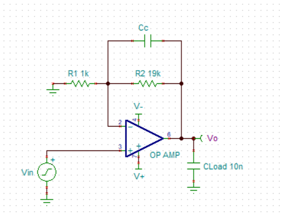
When I read the TI's datasheet of amplifier, it is always suggested that a compensation capacitor should be added in the feedback loop as shown below. But I don't know why and select what value.
1. Could you please share the application note or document to me about:
Best Regards
Zhihong Huang
That is really not very good advice.
Running non-inverting the feedback cap has the effect of shaping the noise gain (and gain in this case) from whatever the DC value is down to 1 at higher frequencies.
Combined with that heavy load cap, it is actually just asking for phase margin problems.
A pretty thorough discussion of phase margin testing and how to get into (and out) of problems appears here -
Part 6 then goes through VFA issues specifically
And then this one tries to clear up gain bandwidth product confusion, which is certainly justified given all the bad data out there,
https://www.planetanalog.com/why-is-amplifier-gbp-so-confusing-insight-12/
Hello Zhihong,
You do not always want to have a feedback capacitor. These are only to be used sometimes, depending on the application and the desired circuit function. To answer your questions.
1. Compensation capacitors can be added for filtering effects. The compensation capacitor may be used to reduce bandwidth, for example in a case where that signal frequency is not needed and the designer wishes to reduce noise. As Michael has pointed out, some feedback capacitors can contribute to stability problems. To learn more about this, please see this presentation.
2. The value of the feedback capacitor will be chosen to create the desired frequency response. It will depend on the circuit designer's intended effect.
3. You can test the circuit using our free simulation software, TINA-TI.
Regards,
Daniel