This thread has been locked.

If you have a related question, please click the "Ask a related question" button in the top right corner. The newly created question will be automatically linked to this question.

TLV9102: Short Circuit Protection via Thermal Protection

Part Number: TLV9102
Other Parts Discussed in Thread: TLV9052

Good day,

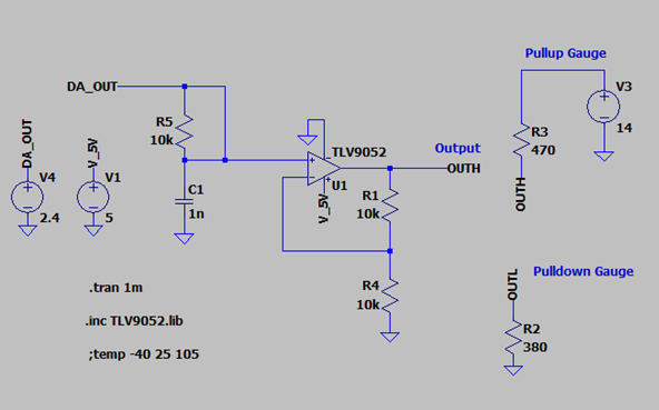
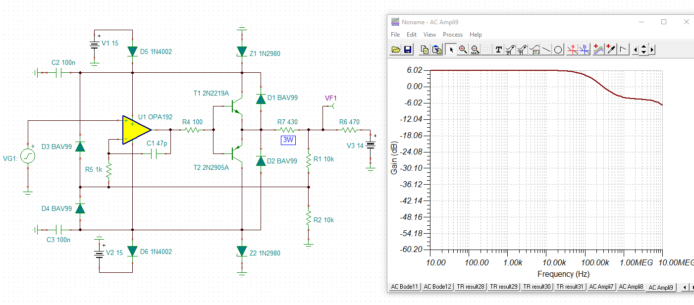
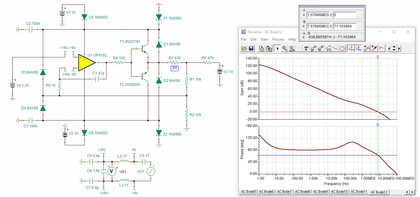
we need to implement a current source and sink with a TLV9102. We have to protect the output against dead shorts both to 14 VDC and GND. In the Datasheet it states that it can handle a short to ground. But can it handle a short to 14 VDC when the output of the opamp is set to 0.5 volts?

Will the Opamps thermal protection kick-in fast enough to prevent damage? We need to hold the short circuit for 1 minute.

  • Hi Louis,

    even if the OPAmp will survive this torture, the thermal shutdown is definitely not intented for repeated use.

    Can you show a schematic?

    Kai

  • Hi Louis,

    What is the positive power supply of the circuit? If 14V connected to the output is greater than the power supply then the internal ESD diodes will turn on and current will flow. This can damage the device is the current is not limited to less than 10mA by a series resistor. 

    Also, depending on the current the op amp has to sink due to the 14V connected to the output, the device output voltage may collapse due to output current vs. output voltage limits of the device. Please see Figure 14 - 17 of the datasheet. So while the output voltage is expected to be at 0.5V, it may actually be at different voltage due to limitations of the device.

    I do not have specifications for how long it takes for the thermal protection to turn on. Since the thermal protection begins to turn on at 140C and the maximum junction temperature is 150C there is room for the device to heat up slightly while the thermal protection turns on before the device is damage. I'll see if our designers can give me any guidance on how long the thermal protection takes to turn on.

    Thank you,

    Tim Claycomb

  • Hi all,

    Thank you for the feedback.

    Here is the schematic. What makes it tricky is that we need to drive an output voltage between 0.5 and 4.5 VDC with either a pull-up gauge connected (represented by R3 and V3) or a pull-down represented by R2. This is normal operation, where it will operate at 99.9% of the time. But we have to test for accidental short circuits for up to 1 minute. That means R3 and R2 can be zero.

    The opamp is supplied with 5V, we have to source or sink current of about 30 mA.

    Polyfuses are also slow and have high resistance, so these are not an option. Any other ideas? Or will the OPAMP survive the test?

  • Hi Louis,

    If R3 is 0ohms the device will not survive. This will cause the internal diode from the output to V+ to turn on and conduct current. Please see Figure 40 in the TLV9052 datasheet for a schematic of where ESD diodes are inside the device. If this current is not limited to less than 10mA the device can be damaged. I recommend taking a look at our TI Precision Lab Videos on Electrical Overstress (EOS). In the first video of the EOS series we discuss ways to protect the device against damage.

    Thank you,

    Tim Claycomb

  • Hi Louis,

    I would probably do it this way.

    Large signal response:

    Small signal behaviour:

    The situation with R6=0:

    louis_opa2192.TSC

    And the phase margin:

    louis_opa2192_1.TSC

    Kai

  • Hi Kai,

    Thanks for the option above! I did take a look at it. Unfortunately we only have a 5.5 VDC positive supply and we need a solution that costs around a euro. I have decided to use the dual opamp we currently have the TLV9102. The first stage will be used as a constant voltage supply protected by a diode on the output. This will allow a short or connection to 14VDC to not cause any damage. Shorting it to GND will be within the spec of the Opamp

    The second OPAMP will be a classical constant current source with a BJT NPN. Downside is that we need to do more in Software and control the two circuits independently but that we can do.

  • Good luck :-)

    Kai

  • Hello Louis,

    With a 5V supply and an output range of 0.5V to 4.5V, the sink driver must be less than 17 ohms and source driver less than 42 ohms. A sourcing diode check value will drop more than 0.5V all by itself not counting the VOH loss from the current flow. Ther load needs to be lightened or the output range reduced. Otherwise a power amplifier will be needed to drive the loads.