This thread has been locked.

If you have a related question, please click the "Ask a related question" button in the top right corner. The newly created question will be automatically linked to this question.

THS4275: Temperature-induced Oscillations

Part Number: THS4275
Other Parts Discussed in Thread: THS4271, OPA820,

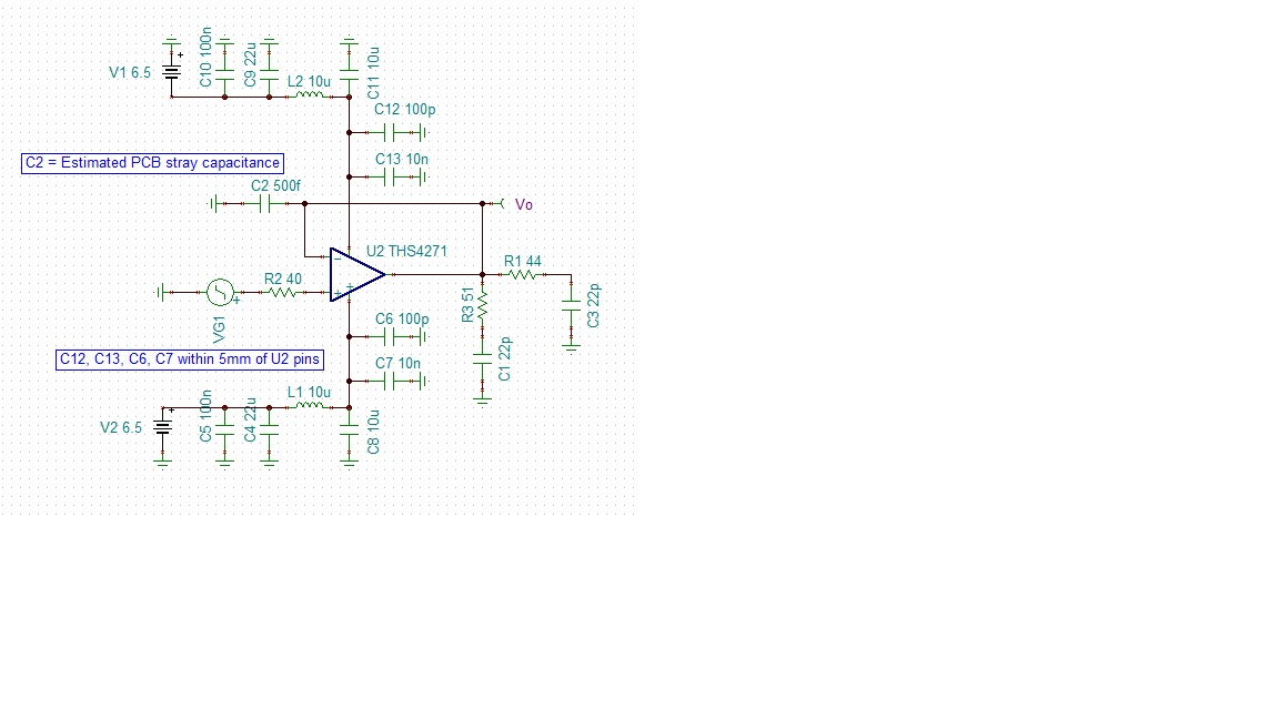
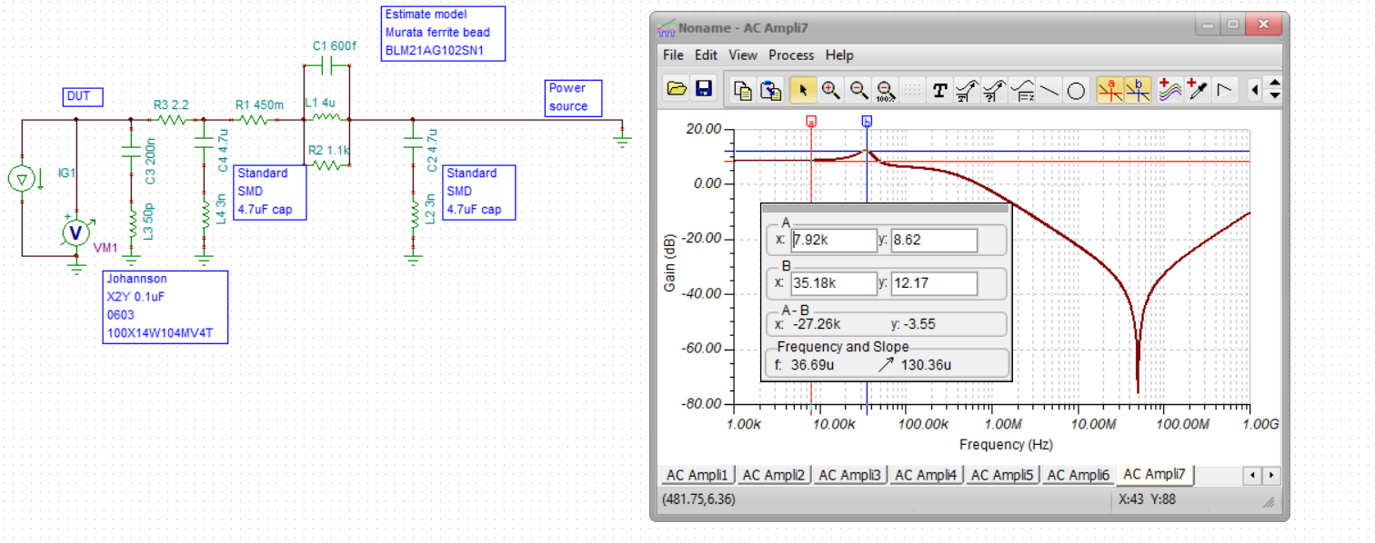
The data sheet for this parts warns that above a variable temperature threshold, the device may exhibit unpredictable low level oscillations. We have a design which uses these parts and up to now, has never shown an indication that oscillations of this sort may be present. However, we have recently done a re-spin of the board and several of these devices are now showing anomalous behaviour, one explanation for which could be the  presence of a low-level oscillation in the 100s of MHz region. To know if this oscillation is a manifestation of the temperature-induced oscillation mentioned in the data sheet or something quite different, e.g. a loop stability issue, I really need some additional information on the characteristics of temperature-induced oscillation if it occurs :- particularly what sort of frequency it would be at, what sort of magnitude and how is it best modelled - voltage source in series with the inputs, voltage source in series with output etc.

Any help with this would be much appreciated.

Robert Phillips

  • Eventually, a schematic will be needed - ideally a TINA file - the folks that put that note into the datasheet are long gone - Kind of unfortunate they proceeded to release a part with this issue.

  • I went back and read the THS4271 datasheet on this topic, put a lot of effort into describing what was apparently a well understood phenomena, why not fix it - also mentioned the TS4211 as an oscillation free alternate. 

    Implies it is a bias setup oscillation, not much you can do externally about that. But at minimum, lets check you decoupling, can you send full schematic with decoupling details. Sometimes if we go to X2Y caps, the supply set up is happier.

  • Below is a screen-shot of a schematic which includes the decoupling components and a few of the parasitic PCB effects.

     - would have up-loaded the TINA .tsc file, but I can't find a file upload option.

    The device mentioned as an alternative has a much worse input voltage noise unfortunately. I've looked at a number

    of other parts from TI and others and so far not found one with the same combination of very low input voltage noise

    and high speed performance - maybe that's why it is still listed as production status.

    It is odd that if they knew all about this problem but didn't just fix it.

    As I said at the start, what I really want to know is some indication if this temperature-induced oscillation, should it

    occur, is a high frequency effect or a very low frequency - it could be either and the data-sheet gives no clue. If I

    knew this I would be able to say whether the high frequency oscillation I can sometimes induce in the re-spun

    PCB is due to the chip fault or is being caused by something else which I might be able to fix.

  • Well Robert, 

    1. I assume those 10uH are ferrite beads, if not they should be

    2. What are you doing with the disable and the reference pins? 

    3. That is a pretty heavy AC load there

    4. +/-6.5V is less than absmax 15V (tells me this is a Bicom2 part), but pretty high

    5. Yes, 3nV unity gain stable 400MHz true gainbandwidth product is kind of unique. THe OPA820 is in that direction but not there. would need to drop to +/-6V

    6. 

  • Oh I see now your schematic says THS4271, while your lead comment is the THS4275 - so no shutdown and reference pins. 

    To attach a file, use the paperclip symbol across the top

  • The THS4271 model was used as the TI website only offers this one.

    The Ref pin on the THS4275 is strapped to analogue ground.

    The En pin is actively driven but is connected to a 330pF, other side of which goes to 
    analogue ground.

    The 10uH is a Coilcraft 1008LS-103-XJL_

    Do you know if  the TINA-SPICE model includes anything to simulate the temperature-
     related oscillation mechanism?

    In the application, this circuit only has to handle signals in range 100 KHz to 50 MHz but
    with a very flat frequency response over that range and very rapid recovery from
    transient O.P.overloads.

    Thanks for suggestion about OPA820 - I'll revew it, could poss trim down power rails voltages
    so long as I can still get enough linear O.P. swing. 

    The paperclip is described as 'insert' , below is the result of using it to insert a .tsc file
    - if you can recover the .tsc file from here please let me know for future reference.

    Regards

    Robert Phillips

  • No robert, you did not get the tina file inserted yet. 

    Customer sim models are very simplified from the full cadence design files - Those would probably have shown the marginal phase margin in the supply setup, but the TINA file will most likely not - usually just current sources to set up the amplifier stages. Also, getting a shutdown feature into the TINA model is problematic and often not done. 

    Hard overdrive recovery is seldom specified nor modelled. One exception is the OPA688 with output limiting, but its noise is probably too high. 

  • Oh and just to be clear, the 2002 THS4275 would not be very easy to support now as all those folks are long gone. 

  • Hi,

    Tried upload again using the 'insert' button.

    I understand that overdrive recovery is not spec'd for the THS4275, but we have found by trail and error that it
    is good enough for our application which is ultrasonic non-destructive testing BTW.

    THS4275 Amp1 incl. Decoupling 29_07_20 #1.TSC

  • Yes, that came into TINA this time, Yea ultrasound NDT is a stress on that first stage, medical does a T/R switch to protect the receiver from the pulse. 

  • So Robert, 

    at the end of the day, we are sort of groping the dark here for answers. Something that goes into and out of oscillation over temperature is by definition low phase margin to begin with. Even if you can convince yourself that your nominal design seems ok, how about that batch of parts shipping 5years from now? 

    Anyway, to give you something practical to try, I was working on better decoupling models some years back with this result - 

    And what I was looking for here was low resonant peaking in the impedance looking out of the supply pins, this does that nicely, nothing in the amplifier TINA model will show any difference using this, but your board might. I also would suggest a supply to supply x2y cap - long ago, we were testing that and seeing better HD2. 

    Here I modified your file to use these supply decoupling models 

    THS4275 buffer with better decoupling.TSC