This thread has been locked.

If you have a related question, please click the "Ask a related question" button in the top right corner. The newly created question will be automatically linked to this question.

OPA462: OPA462

Part Number: OPA462

Dear Sir/Madam

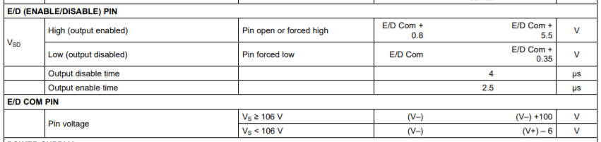
I am using this amplifier for making a Howland voltage to current converter. I will supply the amplifier with +-30V.  I read the datasheet but I am a bit confused about which is the best solution to connect the E/D an d E/D_COM pin. Would it be an efficient way to connect the E/D pin through 1M resistor to V+ and also to a microcontroller pin that provides an external 5V? And also the E/D_COM pin should it be grounded?

Kind regards,

Androniki 

  • Hello Androniki,

    OPA462 datasheet Section 7.3.4, Enable and Disable, provides full details about how to use the E/D and E/D COM pins. Additionally, the Electrical Characteristics table on Page 6 and partially repeated below provides their voltage ranges.

    You can connect the E/D COM pin at any voltage from V- to (V-)+ 6V when using +/-30 V  supplies. The most convenient E/D COM level that most users use is the system ground of 0 V. If the E/D pin is left open a weak internal 1 uA current source will pull up the pin and the OPA462 will be automatically enabled (output ON). However, the pin may pick up noise from nearby sources on the PC board and the OPA462 output could momentarily disable.

    A more robust plan to enable the OPA462 is to bias the E/D pin per the table below. If you connect E/D COM to 0 V, then E/D should be set between +0.8 V and +5.5 V to enable the output. An easy way to do that would be use a resistive voltage divider from the +30 V supply to ground. For example, if it is decided to set the E/D pin to +3.0 V, then the upper divider resistor could be set to 100 kilohms and the lower divider resistor to ground at 11 kilohms. The voltage at the divider point would then be close to 3 V. 

    The issue with using a 1 MEG resistor from the +30 V supply is we don't know how much current the E/D pin is actually going to draw. If the current is low there is the risk of putting an over-voltage on the E/D pin. It is unlikely the pin would be damaged because the 1 MEG resistor would very much limit the current. However, I think it is always better to go with a design that assures the op amp pins are maintained within their specified ranges.

    Regards, Thomas

    Precision Amplifiers Applications Engineering