A related question is a question created from another question. When the related question is created, it will be automatically linked to the original question.
If you have a related question, please click the "Ask a related question" button in the top right corner. The newly created question will be automatically linked to this question.
LM7301: When used as a simple buffer, Positive input loads down sensor that can't drive < 80K ohms.
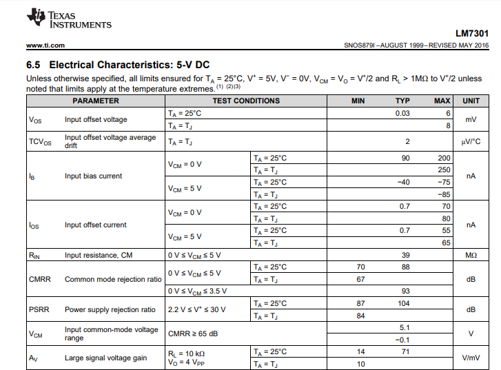
Well, when I disconnect the op-amp from the sensor, the sensor's output voltage goes up to the correct value. Thus one might reasonably assume that the input impedance of the LM7301 is nowhere near 39 mega ohms. Perhaps that was 39 milli ohms?
This is not the first time I've seen this problem, unfortunately, I'm stuck using this part as we spent a great deal of time and money qualifying it for use in our product. Perhaps you could describe how the part functions "beyond the rails". The positive input behaves quite strangely particularly near the rails. Frankly to call this part an op-amp at all is really stretching things.
Well Robert you must consider also the bias current required by the input - this is a DC level required for operation where the input impedance is considered the small signal modulation of that current with voltage - this is a PNP negative rail input device and the input current flows out of the pin - could that be messing up your sensors DC operating point? Typical part seems to be in the 100nA region out of the V+ input
Oh and Robert I was looking closer at your comment about RR input. Yes,this is one of those crossover type input stages that pass control between two input stages and the input bias current actually flips polarity.
Really kind of an old version of this type of part - later, true RR input devices came along that have an on board charge pump to provide an input stage bias > supply applied, normally called zero crossover type parts.
Here is a good short article on this type of input stage by Bruce Trump - going through that crossover region is going to look like a big change in impedance,
I can assure you that the input impedance is not 39 milliohms. Like Michael mentioned, the input bias current of the device might be interacting with your sensor causing the output voltage to shift.. What type of sensor are you connecting to the input? Do you have a part number of the sensor you can share?
Well, there is something going on, but current flowing out would likely boost the output voltage.
I have had this problem with 1 uamp per deg K current sourcing temperature sensors and also with digital pots with source impedances in the 20k range. When I tried to use spice models to get a feel for what might be happening no simple model (like a small constant current source) seemed to fit well. I was able to get a reasonable fit at some operating points by assuming a relatively low input impedance for the op-amp like 50k.
I have a spice model for the device (from National) which appears to be reasonably detailed but does not show the affects I'm seeing. which are pretty obvious.
I am using a Honeywell humidity sensor HIH-4000-003. It's powered from a 5v voltage reference capable of sourcing 10 ma. Way down at the bottom of spec they added a note that the minimum value of resistor it would drive is 80k ohms. It directly drives the positive input of the LM7301. When I disconnect it from the 7301, the voltage is as it should be. When I disconnect the 7301 but put a 50k resistor across the output, the voltage goes down a similar amount.
Well, you'd think that was what was meant by "minimum load resistor". If this were a voltage regulator, it would. And that's what I thought initially. Then I went searching for the maximum current it's output could source. No such spec. Huh, strange. So I put a 20k resistor load on it. That lowers the output voltage even more that the 7301. Disconnecting both yields the correct output voltage.
Nothing like putting the components on a bench to see what they really do...
Back ti the input of the 7301, As it's being used as a source follower buffer, the output which is connected to the negative input is always at the same voltage as the positive input. That makes the common mode voltage zero. Is there anything strange about its behavior at a zero common mode voltage operating point?
There shouldn't be an issue with a common mode voltage of 0V with a single supply of 5V. However, the common mode voltage is equal to the input voltage (output voltage of the sensor) when in a buffer configuration. So is the sensor outputting 0V?
The common mode voltage is equal to the average voltage of the input pins of the device. Since an op amp always drives the inputs equal to each other we can say that the common mode voltage is equal to the voltage at the non-inverting pin of the device.
One thing to note with if there is an input voltage of 0V the op amp will try to drive the output to 0V when in a buffer configuration. But due to the output swing limits of the device the op amp will not be able to output 0V.
I think the LM7301 got damaged during the experimenting. So I would take a fresh LM7301 and check again. Guarantee that the sensor and the LM7301 are always and at any time connected to the same supply voltage (+5V), even during power-up and power-down.
Ah, sorry, was not tracking your definition of common mode voltage. The sensor has an offset at 0% RH of .782 volts, and an output of 3volts at 75% RH. So no need to go to zero volts on the output.
At the moment the sensor in front of me is generating 1.95v in 54.5% RH The expected value from the sensor is about 2.5v. Another board measured 2.3v connected to the 7301, 2.5v disconnected, and 2.4v with only a 50k resistor across it.
Well, the sensor is powered by a 5V reference, which feeds a 3080 regulator directly to generate 5v for the op-amp. There is 10uF on the output of the regulator so some few milliseconds of lag might exist. Hard to imagine that would damage an op-amp, but hey, beats me why these parts seem broken.
Is there a load on the output of the LM7301? The LM7301 doesn't have much output current drive capability so a heavy load can effect the output voltage. See Figure 13 in the datasheet.
I took a look at the humidity sensor datasheet you are using but I didn't see what might be causing the problem in the datasheet. The main causes of error would likely be input bias current (200nA max) interacting with the impedance of the 80k resistor and sensor impedance. But I would not expect that to make the voltage change by 100's of millivolts. You could try testing at CMOS device such as the TLV9001 to see if the issue goes away. I know you have to use the LM7301 due to qualification but it would still be a test to try.