This thread has been locked.

If you have a related question, please click the "Ask a related question" button in the top right corner. The newly created question will be automatically linked to this question.

OPA567: what voltage should we expect on Iset pin (pin6)

Part Number: OPA567

Hi,

I tried to make my IFLAG high after EN is high with Vin and Vset are both 2.5V but failed.

 I was checking any potential cause and I found my Iset pin (pin6) is always 0V. I thought I will measure a +1.18V.

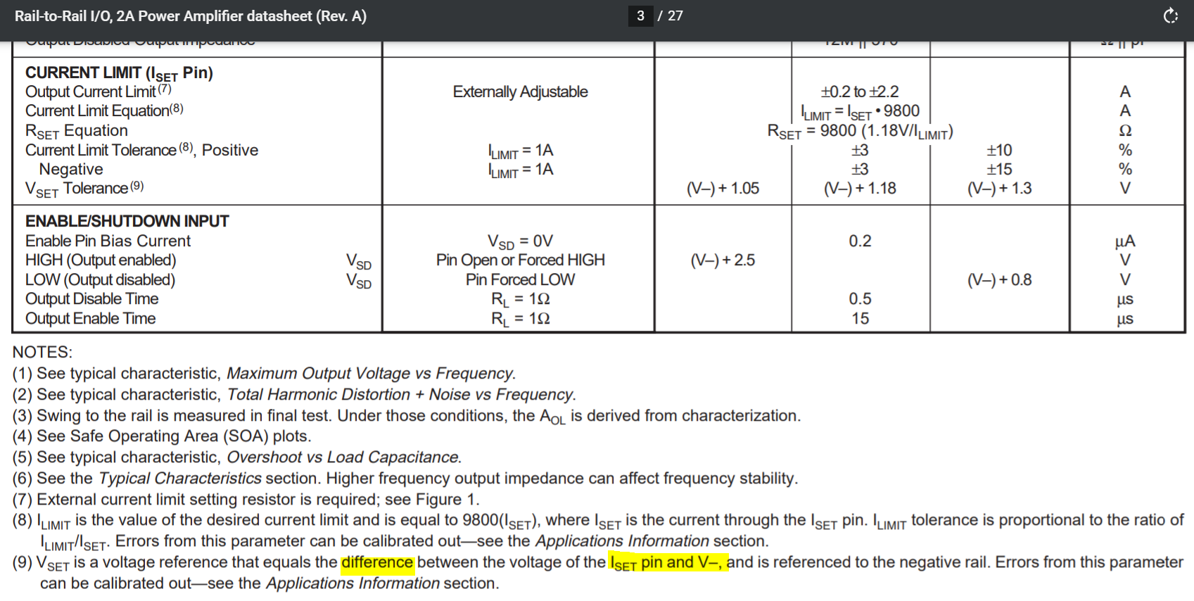
Will there really be a voltage greater than 0V on Iset pin as what described on p.3?

Thanks.

  • Hello Hsinru,

    It sounds like you might have some damaged OPA567 devices.

    The OPA567 datasheet on Page 14 states with regard to the IFLAG function:

    "The output signal of the IFLAG pin is compatible to standard logic in single-supply applications. The output signal is a CMOS logic gate that switches from V+ to V– to indicate that the amplifier is in current limit. The IFLAG pin can source and sink up to 25µA."

    Make sure that you are not loading the IFLAG pin too heavily. It pin is intended to drive gate inputs.

    Regarding your OPA567 question: Will there really be a voltage greater than 0V on Iset pin as what described on p.3?

    Yes. Figure 2 in the OPA567 datasheet shows a simplified ISET circuit. ISET is a reference current that establishes the current at which ILIM occurs and remains constant during operation. There is an internal 1.18 V reference that sources an ISET current equal to ILIM / 9800. This can be verified using information in Figures 1 and 2. You should measure about 1.18 V at each pin 6 for whatever ILIM you select. The graph below from the OPA567 datasheet shows the ISET current as a function of the supply voltage. The ISET voltage may vary as the graph indicates, but the voltage is always present and about 1.18 V when power is applied.

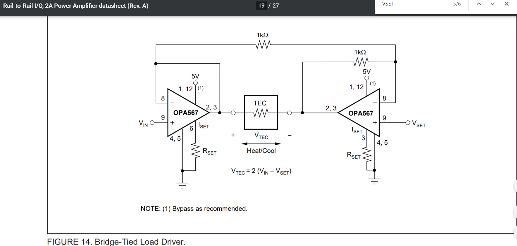
    Note that there is a typo in Figure 14 where pin 3 is labeled ISET for the righthand OPA567. It should be pin 6 for ISET.

    Make sure that the thermal pad under the OPA567 package is soldered to an appropriately sized PC board pad that is connected to the V- potential. Problems can be had if this isn't observed.

    Regards, Thomas

    Precision Amplifiers Applications Engineering

  • Thanks, Thomas.

    After removing a series of an inverter and a NMOS on IFLAG pin. I could measure a voltage on ISET pin now.

    By the way, I want to use IFLAG signal to also enable/disable the ENABLE pin (like the combinational logic of TFLAG and external enable signal). Is there any reference design to follow up? Or recommended components for IFLAG to use in the design?

    Thank you so much.

    Hsinru


  • Hi Hsinru,

    Glad that the OPA567 ISET is now operating as you expected. The TFLAG uses comparable CMOS logic and high/low logic levels as the IFLAG function. Therefore alternately, you could apply the Figure 6 Enable/Shutdown circuit using TFLAG.

    Regards, Thomas

    Precision Amplifiers Applications Engineering

  • Thanks. I will try a comparable CMOS logic on IFLAG.


    Thanks you so much

    Sincerely

    Hsinru