A related question is a question created from another question. When the related question is created, it will be automatically linked to the original question.
If you have a related question, please click the "Ask a related question" button in the top right corner. The newly created question will be automatically linked to this question.
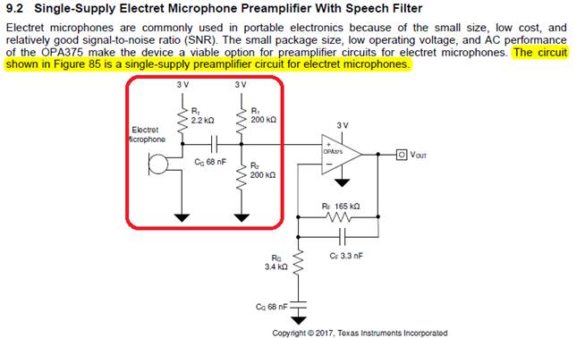
I think only the part labeled "Electret Microphone" is internal to the microphone. A quick search online shows that most electret microphone structures consist of the microphone structure with an amplifying transistor. You can double check your microphone's data sheet to verify this. It should be shown there. The R1 component is external and is used to complete the gain of the common source amplifier. The CG component works to block any DC signal and finally the last two resistors set the DC biasing voltage.
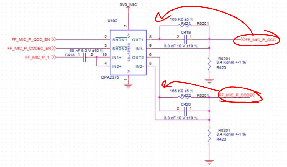
My comment on the circuit would be, are you taking the output at the spots labeled "FF_MIC_P_QCC" and "FF_MIC_P_CODEC"? Why not take the output at the previous node where the output of the op amp is? I am not really sure how you are implementing the circuit, so perhaps your way is correct. I believe there are different ways to do this. One approach is outlined in section 9.2 of the data sheet, as you have mentioned. Another approach is described in this Analog Design Journal entry.