This thread has been locked.

If you have a related question, please click the "Ask a related question" button in the top right corner. The newly created question will be automatically linked to this question.

CCS/AMC1302: Delay in Current Sensing leads to Offset and Error

Part Number: AMC1302
Other Parts Discussed in Thread: TMS320F28377S, , C2000WARE

Tool/software: Code Composer Studio

Hello everyone,

we are currently developing a 3-leg grid inverter. During a test, a problem has occurred where we could need some support.

The inverter runs with 70 kHz and is controlled with the Delfino TMS320F28377S.

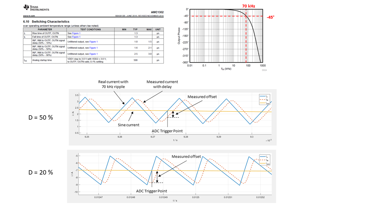
For the current sensing we are using a shunt and the AMC1302. The delay between input and output is specified here with about 1 to 3us. Looking into the phase response we got -45° phase shift at 70 kHz. This causes a not negligible error in the measured current. Our nominal current is about 10 A RMS and the ripple is about 2 A.
The error in the current measurement can reach up to 1 A, which leads us to other problems. The error is also dependent on the duty cycle.

We have already tried to compensate for the error in software, but with this big error it is not possible to make this work satisfactorily.

Here are some details from the datasheet about the delay and below I have tried to visualize the problem.

Is there a good way to compensate the error in software?
Do we need to consider another sensig IC with more bandwidth?

We are looking forward to feedback. Thank you very much in advance.

Best regards,

Simon

  • Hi Simon,

    Can you please share your AMC1302 schematic? 

    The bandwidth of the AMC1302 is 280kHz which should be more than sufficient to measure a 70kHz signal. As you've pointed out and as common with all analog sensing, there is delay associated with the device and signal chain, however I would not consider this an offset error as it is simply lagging the real signal. 

    What are your end goals of the system? Are you concerned about over-current protection? What is your timing requirement?  

    If you are ok with it, I would be interested in discussing your system needs in greater detail offline. 

  • Simon,

    Is absolute accuracy the problem? or is it more of an issue from a loop stability perspective?

    We do not have a ready technique to help with this kind of phase shift. 

    One suggestion I can offer is to change the sampling point to account for the phase shift. 

    You can also consider adding additional filtering to remove the 70kHz component all together. 

    -Manish 

  • Hi Alex,

    thank you for your answer.
    As we want to develope a grid inverter, we need to implement an RCD. Our goal is to keep the sum of all three output currents about at zero. For that reason, we need to measure the current as accurate as possible. We think if the error stays below 10 mA, we can control the RCD current sufficiently.

    We have taken the schematic almost exactly as it is shown in the data sheet.

    Yes, the bandwidth is sufficient considering the magnitude of the frequency response. Howerver, the delay of the AMC1302, which is about 1 to 3 us, is quite huge compared with our switching period, which is 14,3 us. So we are not able to measure at the right time and this leads to an error in current of up to 1 A. 

    Best regards,
    Simon

  • Hi Manish,

    many thanks for your reply. 

    Yes, it is about accuracy as I mentioned it in the reply to the answer of Alex.

    We already tried to sample later. One problem is, that the delay differs from device to device a bit, so it is not constant. The other problem is that if we move the trigger point too far, we hit the switching point of the mosfets and there is a lot of noise.

    We also discussed about filtering the 70 kHz ripple, but then we make the controller much slower. This would be an option, but we wouldn't like to do this :) 

    Now, we are discussing about sampling a switching period as often as the ADC allows us to, approximately 20 times, and taking the average value. With this approach we can achieve more accuracy and reduce the control frequency only by half.
    What do you think about this?

    Best regards,
    Simon

  • Simon, 

    For RCD feature it may be worthwhile to split the current sense channel onto two ADC pins.

    One of the ADC pins receives the less filtered signal used for control.

    And other ADC pin receives the filtered signal for RCD protection. 

    What is the time window in which RCD needs to be detected? Any specific standard being met here? 

    -Manish 

  • Hi Manish,

    thanks for your feedback. That would also be an idea, but it would also require a change in the hardeware, which we want to avoid in first place. If there is no other solution, we will consider this.

    Here the specification for the RCD.

    A sudden step of 30mA or more in the RCD-current leads to a failure after 300ms if the step does not disappear.

    A sudden step of 60mA or more in the RCD-current leads to a failure after 120ms if the step does not disappear.

    A sudden step of 150mA or more in the RCD-current leads to a failure immediately.

    A steady state error of more than 300mA leads to a failure after 300ms.

    Many tanks and best regards,
    Simon

  • Simon,

    Thanks for sharing the details, 

    "A sudden step of 150mA or more in the RCD-current leads to a failure immediately."

    What is qualified as immediately ? 2us ? 10us? 

  • Simon,

    Following up on the call, we discussed about oversampling the signal to increase ENOB. 

    The only example for DMA transfer is here 

    C:\ti\c2000\C2000Ware_3_01_00_00\device_support\f2837xd\examples\cpu1\dma_gsram_transfer

    I'll suggest posting the DMA question separately so it can go to the subject matter expert.

    -Manish