A related question is a question created from another question. When the related question is created, it will be automatically linked to the original question.
If you have a related question, please click the "Ask a related question" button in the top right corner. The newly created question will be automatically linked to this question.
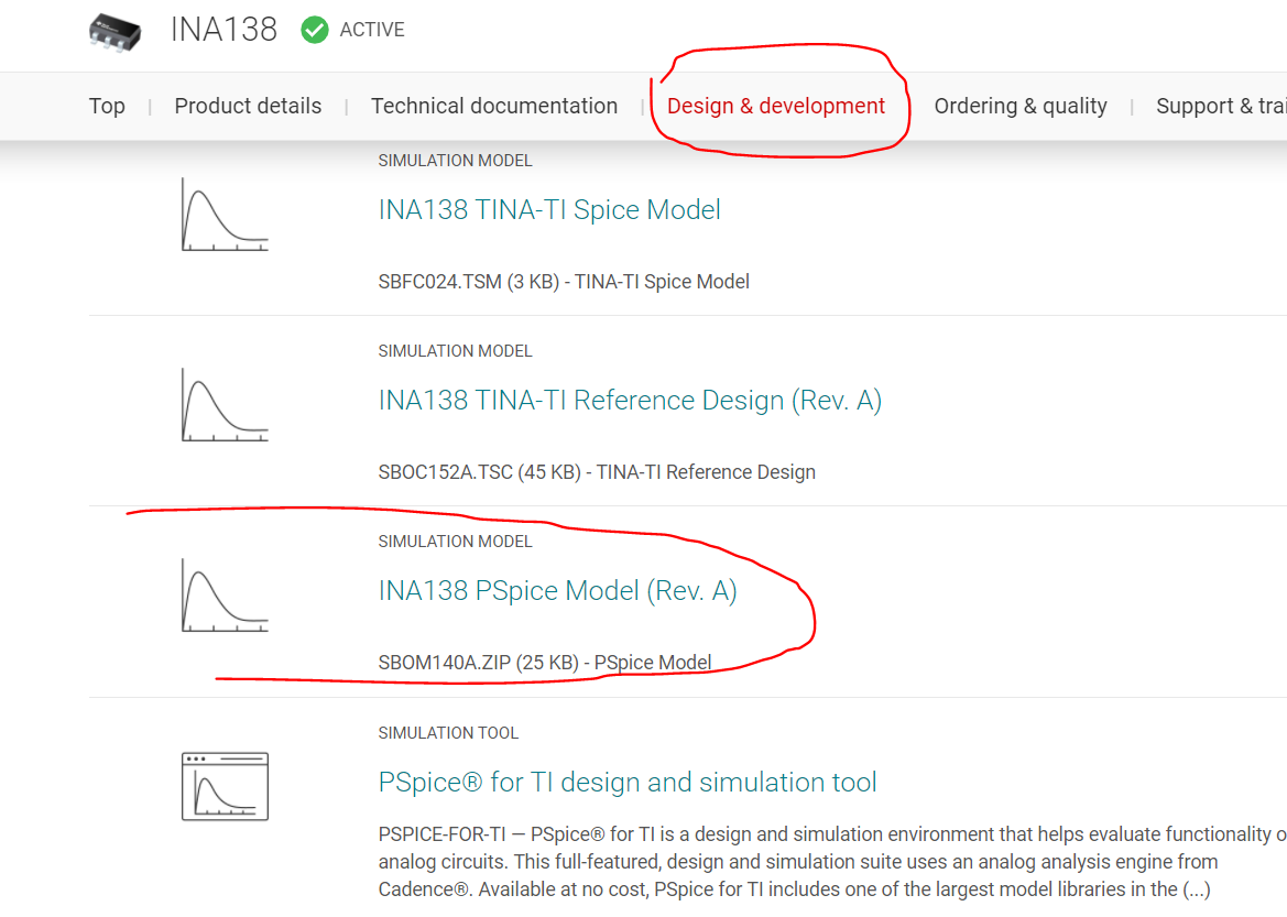
Well Marks, if you drill down here and click on the circled line it will open the zip files including the .lib version - where it works or not in LTSpice is the next question,
And here is that file if you can import directly from here,
I will try the .lib file to include it at LT Spice.
Meanwhile - I want to limit the sense voltage on pin3 and pin4 cause the external circuit could allow a higher current dropping a high voltage on Rs (in my case 10...22R).
Any problems at the INA if I use R1=R2=200...1kR with a diode in forward direction to limit the voltage to 0.7V?
Thanks for using E2E! Micheael is correct that this is the location of the files for PSpice/LTspice.
If you have issues importing into LTSpice, we also have TINA-TI, and now our new PSpice for TI products that can help you evaluate here.
Regarding your question, it's hard to visualize what you say is going on without a schematic. Can you post a schematic that shows the relevant reference designators you're calling out?
thanks for the advice. Have integrated the lib file within LT spice. Thanks for the advice with your tools. Had never a look on it. But normally we use a lot the LTspice here or Pspice what I dont have.
1.) That one seems to work in principle. When V1 is positive I have no issues. An if R1 and R2 are low enough:
2.) It doesnt work when R1, R2 are getting higher. It seems there is a huge current flow into the INA?! What is the input impedance here at that sense pins? Thought pretty high resistive. I have a scenario where I have a voltage >=100V + together with the protection diode I need to limit the diode current. That is lets say in the kR-Range but that makes it impossible to sense properly cause of the voltage drop on R1,R2...
3.) It doesnt work when I use a negative voltage vor V1. I changed the sense pins that the +Pin is more positive then the -Pin for sensing. Shouldnt it work also?
To summerize:
* is the current consumption into the sense pins really existing?
* how can I protect the sense pins from a higher voltage than 500mV, 2V if not with a diode + R1,R2?
* why is it not working when I my supply is a negative voltage?
Have a look at this forum post. This might be the current spike you are seeing?
Regardless, the resistance on each of the lines is only 5kΩ's, as shown in the datasheet (these are technically transimpedance amps, so the input impedance is small and the output impedance is large):
The addition of resistors R1 and R2 are going to significantly change the input structure here, and are not recommended with this family of amplifiers (we recommend output filtration, since the output impedance is large here). Do you require a current out response here?
thanks...no good news that the input impedance is so low.
Regarding to your link to the other post - here they are also using a 1kR :-)
So right now I have pretty no idea how to limit the voltage on the sense pins.
What do u mean with current out response? Behind the INA there is an ADC drawing not so much current and also a enhanced 400V circuit using an external transistor as u recommended.
But finally - why isn't it working with the -15V and the swopped sense pin configuration?
This device provides a current output rather than a votlage output, and is why the gain is adjustable set by a resistor, as Io*Rg = Vout.
The reason the current setup is not working is because the device is not seeing a valid common mode at the input pins. Compared to 10kΩ, you can think of the 5.5Ω and 10 ohm resistor in the path as practically a short circuit to the load. This implies that the voltage seen by both the input pins is -15V, and therefore the VCM is -15V. The allowable range for the device's common mode is 2.7V-36V.
Can you work with a voltage output device? We have some recommendations that can measure this negative of a common mode, but they are pre-fixed gain parts that provide a voltage out, like LMP8602.
sorry...yes of course I'm using the Rg=50kR to get the right voltage for the ADC. The schematic is a bit confusing...the Radc=50kR is not the input impedance of the ADC...its your Rg.
ok now I understood it...the common mode voltage is out of the spec. Haven't realized that.
So which simple ICs instead of the LMP8602 are in capable to measure at negative cm voltages?
Several of our other products might work here, but like the LMP8602, the loop is closed internally and the gain comes prefixed (20x,50x, 100x for the LMP8602).
You can examine other devices that are capable of withstanding -15V common mode here via our parametric table.
I'm not quite sure what is going on in your environment, but I suspect something did not import correctly in the model. Specifically, I think the saturation point is not present. I ran your test setup as it is in TINA-TI, and came out with a different result, showing the device in saturation at roughly 1V below V+, which corresponds to the datasheet worst case condition. In your setup, I have a measured 808.06mV at the sense pins, which is indicating that the diode has turned on and is clamping the pins to that voltage:
Analyzing this number, the 808mV at the sense pins would take the place of IsRs in the output equation (what's measured at the shunt on the other side of the 100 ohm resistors is irrelevant, its what's at the pins that matters), so the expected output at the Vout pin would be .808*50k/5k = 8.08V, which is roughly what you are seeing in your simulation. That indicates to me that your model is simply outputting the actual calculated output voltage rather than showing the device entering output saturation of ~4V. That shouldn't happen, and it would seem that something in the model most likely didn't import correctly, as I do not see this behavior in the TINA model.
Unfortunately, as part of the end user license agreement of LTSPICE, TI cannot provide support for LTspice. As I said, the model should definitely be saturating rather than providing a voltage greater than Vs though, as it does in the TINA sim I attached prior.
TI does offer a free version of PSpice, found here, which might help your analysis here.
Regardless of the state of V+, if the INA138 were to see a common mode of -15V, there's a chance you could damage the device, as per the abs max ratings table:
Even if the input pins were to survive the event, in either case, as the device is not rated for this type of common mode voltage, the output would not be linear, and would not be valid information to be used in the system. I would expect the device to potentially saturate against the bottom rail in response to the sudden change in the common mode, but I cannot say with certainty. The expected behavior here is not something we typically characterize, due to the fact that this is outside of the absolute maximum ratings.
Here the measured values in the lab - ignore the black values, the purple one count. The R1/R2, ADC stuff on the right side is not existing physically...
So if the INA sees 0.67V at its input...I don't know why he forces out around 320uA...
Glad to hear it. While I was digging further into this this morning, I also came across this in section 8.1.1 of the datasheet, so be aware:
So it looks like if the diode is allowed to forward bias (as well as a small amount of headroom prior to turn-on, which looks to be around .648V > .5V), the information from the output of the device will no longer be guaranteed to be accurate.
Regarding the LMP8602, there is a Pspice model in the product folder that you should be able to import, but you can also look at this on PSpice for TI if you want to confirm.