This thread has been locked.

If you have a related question, please click the "Ask a related question" button in the top right corner. The newly created question will be automatically linked to this question.

INA592: Load restriction on the INA592

Part Number: INA592

Hi Team,

Our customer would like to confirm if is it ok to use such a low-valued load to INA592?
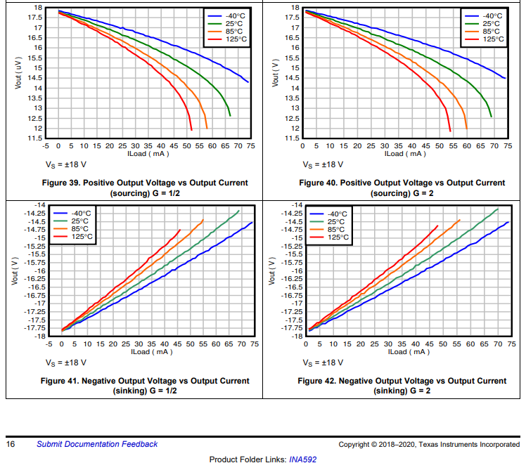
He would like to confirm if it is better than AD8276 (please see figure 20 and fig. 21) where they show the max. output voltage as a function of the output load. From this figure it is clear that for a low-valued output load, the voltage drop is actually pretty bad.

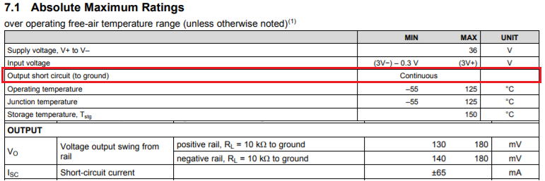
The customer cannot find a similar plot in the INA592. He would like to know the maximum output voltage of the INA592 with respect to both the current and the load connected to the output. 

Please let me know if you have any questions to answer this confirmation of the customer of INA592.

Thanks,

Jonathan

  • Hi Jonathan,

    it's in the datasheet :-)

    And the associated load resistances can be calculated from the figures.

    Kai

  • Hello Kai,

    Thank you for your support in this thread.

    The customer already reviews this figures 39-42.
    According to the customer, The datasheet specifies that for a +/-10 mA current would limit the output voltage to Vss - 1, as shown in Figures 39-42. But those are for a fixed load of 10 kohm (which seems strange, the datasheet shows the current up to around 70 mA, but that would case a 70 V voltage on the load, which seems not possible). He ask this because the datasheet of the AD8276, Figure 21, shows that the output voltage is not only limited by the ouput current but also by the load resistance. And he would like to know if this is also the case for the INA592.

    Do you have any comments on this part?

    Regards,

    Jonathan

  • Hi Jonathan,

    INA592's short circuit current limit to ground is +/-65mA at 25C, which is shown in Figure 39-40. The max. output current varies with Tamb condition somewhat, but the figures are shown the effects. The figures also show the output voltage swing from rail, which is a function of load resistance, I_load and Tamb temperature.  

    The datasheet represented Vout (swing voltage) vs. I_load relationship, R_load can be calculated in Figure 41 and 42.  AD8276 presents Output voltage swing vs. R_load, where I_load can be calculated from the plot in Figure 21. You are able to extract the performance data vs. temperature based on these plots. 

    If you have other questions, please let us know.

    Best,

    Raymond